


As explained in the main page for this project, the overhaul of No. 6 started in 2001, and by 2005 had reached a stage where it was appropriate to start work on the boiler, but this then got overtaken by the project to completely remodel the Moor Road site and construct the Engine House building. By 2014, when work on the locomotive resumed, it became apparent that major boiler repairs would be needed, and once we had done what work we could on the boiler, then an appeal was launched to fund the rest of these repairs.
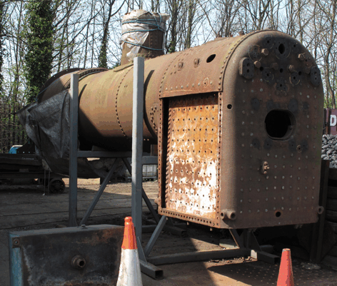
At this time much of our engineering work was focused on the project to overhaul "Brookes No. 1", but once this locomotive was returned to steam successfully in August 2017 then we could start to look again at what needed to be done to the chassis of No. 6. By this time we had acquired a pair of proper boiler stands, and the boiler of No. 6 was the first to be put on them, as shown in the picture below.
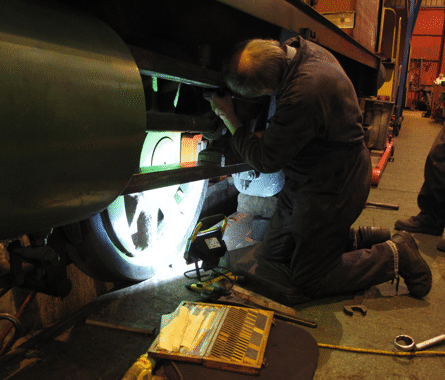
Assessing the work needed for the chassis involved a lot of careful measurement, and one of the main conclusions of this was that the crankpins on the wheels were not as round as they should be. Putting this right involved a little bit of work with a grinder, a lot more work with files, and finally finishing off each pin with emery cloth.
Once we had the pins round, then it was possible to fit the bearings to them, which involved machining out the gunmetal a bit to allow the bearing surfaces to be coated with white metal, and then very careful machining of each bearing to ensure that it fitted properly to the corresponding crank pin. Then the side rods and connecting rods could be painted, and the picture below shows the two painted connecting rods on the ground alongside the chassis, and the left hand side rod up on the footplate.
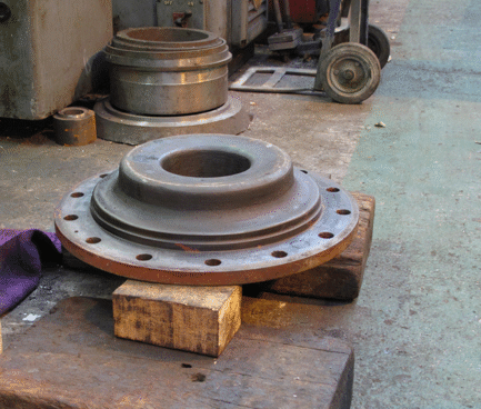
Another piece of work that had been identified by all the measurements that had been made was that the piston rings were sufficiently worn to need some attention. Since we had some material for making new piston rings left over from the overhaul of "Brookes No. 1", we decided to use this and make new piston rings. To go with these we also decided to replace the glands on the rear cylinder covers, which seal round the piston rods. The picture below shows one of the cylinder covers waiting to be refitted to the cylinder.
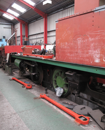
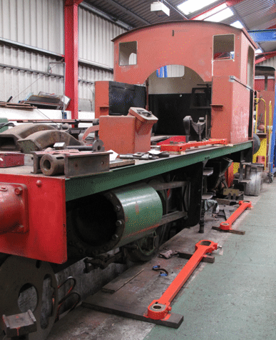
The other piece of work that had been identified by the measurements was the need to fit the crossheads to the slidebars. The slidebars themselves needed very little attention, and so the first step was to adjust the positions of the bottom slidebars on each side, to ensure that they were parallel to the centre lines of the cylinders. This was done by fitting shims at each end of each slidebar, and the picture below shows the left-hand side of the chassis with the bottom slidebars in their correct positions. At this point the front cylinder covers had not yet been fitted, to allow the centre lines of the cylinders to be measured accurately.
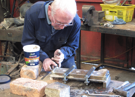
With the bottom slidebars in their correct positions, the next step was to fit the crossheads. These needed to have their centre lines at exactly the right height to match the centre lines of the cylinders, and this involved overhauling the slippers that are mounted in the crossheads, and that slide on the slide bars. As with the bearings, this was done by coating the slippers with white metal and then machining them to fit, and the picture below shows one of our volunteers preparing a slipper for this.
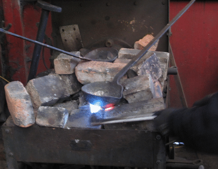
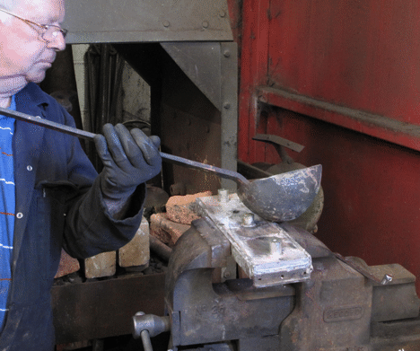
Once the slipper was ready, then a suitable quantity of white metal had to be melted in a ladle, as shown in the picture below.
Then another of our volunteers could pour the molten white metal into the mould that held the slipper, so as to coat the slipper with the white metal, as shown in the picture below.
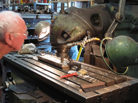
Once everything had cooled down, then the outside of the slipper could be machined to fit exactly into the crosshead, and the picture below shows one of our volunteers doing this on the milling machine.
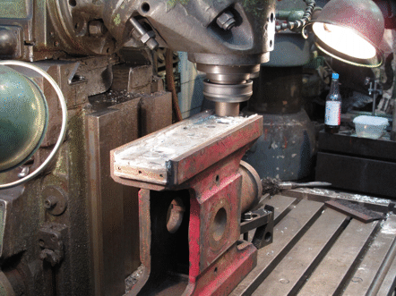
Then the slipper could be mounted in the crosshead, and the surfaces that slide on the slide bars could be machined to fit the slide bars. This too was done on the milling machine, as shown in the picture below.
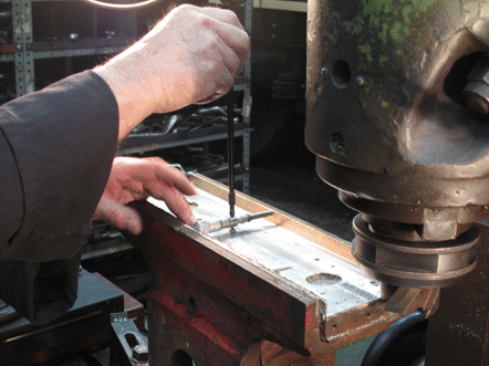
An essential part of getting a good fit between the slipper and the slide bars is careful measurement, and the picture below shows the width of the gap between the sides of the slipper being checked with a micrometer.
Once the crosshead slippers had been machined to the correct dimensions, then the crosshead could be positioned in the slide bars, and the height of the top slide bar adjusted by shimming it to give exactly the right clearance between the bottom and top slide bars. Another of our volunteers is shown in the picture below, measuring the thicknesses of the shims that are needed, using a set of reference shims from the yellow case on the floor.
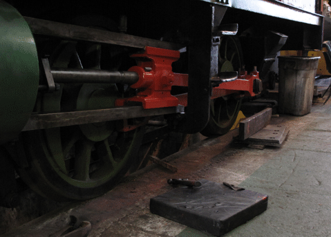
With both slide bars fitted to give the correct clearances for the crosshead, then the side rods and connecting rods could be fitted, as shown in the picture below of the left-hand side of the chassis.
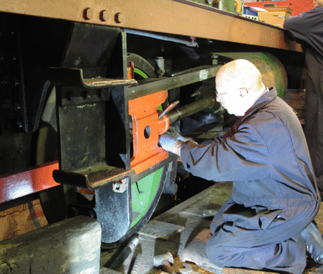
Then, of course, the whole process had to be repeated for the right-hand side of the chassis. The picture below shows one of our volunteers fitting the crosshead onto the piston rod, so that then the cotter pin can be driven into place to hold it tight.
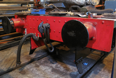
Once everything fitted correctly, with the slide bars, crossheads, piston rods, side rods and connecting rods all in place, then attention needed to be turned to the sanding gear. The sand boxes were found to be fairly well blocked with old sand, and a lot of time had to be spent cleaning this out. Then the sand boxes could be painted and fitted to the chassis, and the picture below shows the rear right-hand sand box in place.
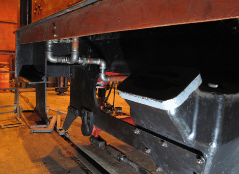
While the sanding gear was being worked on, work also started on fitting the locomotive for vacuum braking, which it had not previously had. The picture above shows some of the vacuum brake piping under the cab, and the picture below shows the front buffer beam with the vacuum brake pipe and hose in place, and behind it the dolly for the brake hose.
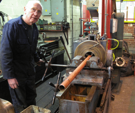
Because the locomotive never had vacuum braking previously, fitting the pipework for it has not been easy, as we wanted to try to keep this out of sight as far as possible. Consequently, a lot of the piping has involved short lengths fitted together with elbows that are screwed onto the ends of the pieces of pipe. Our screw-cutting machine has proved very useful for making the screw threads on the ends of the lengths of pipe, and the picture below shows one of our volunteers operating it to cut the thread on the end of a piece of pipe.
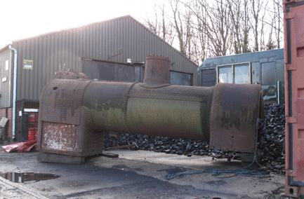
Meanwhile, discussions about the boiler repairs had been going on with various contractors, which had indicated that fortunately the cost of these was likely to be closer to £40,000 than the £60,000 for which we had originally been budgeting. This, together with the prospect that funding which could cover this figure would become available, encouraged us to decide in January 2019 to place a contract with Northern Steam Engineering Ltd. for the boiler work to be done. So, the boiler was lifted off the stands, and the picture below shows it waiting to be transported to their works in Stockton-on-Tees.
The departure of the boiler marked a natural break in the overhaul work, and to reflect this the story of the project is continued on a separate page.
Go to the page for part 2 of the overhaul.
Go back to the main page for this project.
Go to the page "Help Raise Steam in No. 6", which describes the appeal for funds that we needed to set up to help finish this project (although this appeal is now closed).
More Information
Pages about other projects:
- Last Coals to Leeds;
- Project Phoenix;
- Building a Running Shed;
- Overhauling "Brookes No. 1";
- Conserving "Picton".
Other pages provide more information about:

