 The page describing phase 2 of this project explains that phases 2 and 3 of it overlapped a bit, in that phase 2 was concerned with overhauling the frames and the running gear, and so effectively finished once the frames were back on the wheels. Then, phase 3 covers the rest of the re-assembly of the locomotive, but one of the first stages in this was re-tubing the boiler, and this actually started early in July, while the last bits of work on the running gear were being completed.
This page therefore describes phase 3, while the previous page describes the last bits of work in phase 2. Click on the links below to track our continued progress:
- July 2016
- August 2016
- September 2016
- October 2016
- November 2016
- December 2016
- January 2017
- February 2017
- March 2017
- April 2017
- May 2017
- June 2017
- July & August 2017
July 2016
The first step in re-tubing a boiler is to fit all of the tubes into it, by pushing them through from the front, while somebody in the firebox uses a short bar to catch the rear end of each tube and guide it into its correct hole. They then use a depth gauge to ensure that each tube sticks out into the firebox by the same amount.
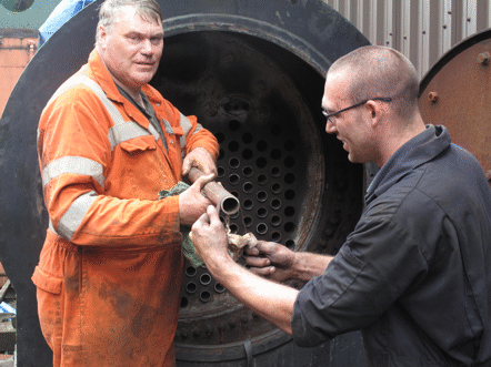
Before each tube is inserted, however, its ends need to be polished with a strip of emery cloth, so as to remove any rust or other dirt which would prevent it from fitting tightly into the tubeplate when it is expanded. The picture below shows two of our volunteers polishing the front end of one of the tubes in this way, before they push it fully into place in the boiler.
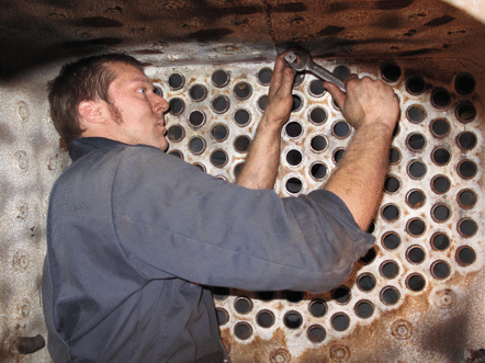
Once all of the tubes have been fitted into their holes, then the process of expanding each tube to fit tightly in the tubeplates can begin. This is done using a tool called a tube expander, which consists of a metal cage that contains a number of rollers arranged round a central shaft and almost parallel to it. The central shaft tapers, and the rollers are mounted into the cage so that they are at a slight angle to the central shaft. Consequently, when the central shaft is turned the rollers gradually pull themselves into the end of the tube, and expand it to become a tight fit. In the picture below one of our volunteers is working in the firebox to expand a tube: usually he would use a ratchet to turn the expander, but since this tube is in the top row it is sufficiently close to the roof of the firebox that there is not room for the ratchet, and so he is having to use a spanner instead.
While this is being done, the other end of the tube has to be held tightly, to stop the tube turning in the tubeplates, but once the first end has started to grip then a second tube expander can be used at the other end, so as to expand both ends at once. Once one tube has been expanded it is marked, to show that is has been done, and work starts on the next one. The picture below shows the volunteer at the smokebox end taking it easy for a minute or two, once all the tubes in the central left column have been expanded, and work has started on the central right column, as shown by the paint marks above the tubes that have been completed.
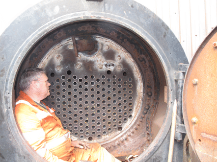
In the picture above it will be noticed that there are a number of holes that have not got tubes in them: four across the top, above the tubes, and then three at the bottom, although only two of these are visible. These holes are for the washout plugs, which are screwed into them, but about once a year they need to be taken out to allow the inside of the boiler to be washed out, to get rid of the sludge and scale that accumulates.
Steady work meant that by the end of July all of the tubes had been expanded, and the picture below shows the two happy volunteers celebrating this milestone. Of course, at this stage no water had been put in the boiler, and experience says that once this is done some more expanding will almost certainly be needed.
August 2016
Meanwhile, back in the workshops the side rods were being refitted, only to discover that the rear left-hand axlebox had not been fitted correctly, despite all the care that had been taken over the measurements. The error was only a matter of 20 thousandths of an inch (half a millimeter in metric units), but it was enough that as a result the left-hand side rod would not fit.
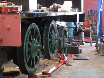
The rear end of the frames therefore had to be jacked up again, as shown in the picture below, so that this axlebox could be dropped out and the shims adjusted to that it would fit correctly. The side rod is lying on the ground, ready to be tried again once the axlebox has been refitted. Also on the ground can be seen two of the eccentric straps, which had not yet been fitted onto their eccentric.
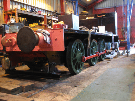
Once the shims in the axleboxes had been adjusted, it was refitted and the frames lowered down again, and then the side rods could be fitted, as shown in the picture below.
With the side rods fitted, the next step was to fit the connecting rods, which link the crossheads to the driving axle, and so transmit all the power from the pistons to the wheels. The picture below, which was taken from the cab footplate, shows the two connecting rods in place. The next step in assembling the motion will be to fit the four eccentric rods, which connect the eccentric straps (that can be seen in the picture, already fitted round the eccentrics) to the two links which are the main part of the valve gear.
This picture also shows very clearly the construction of the frames, with the two main frame plates (one on each side) running the length of the locomotive, and the various cross-pieces (known as the frame stretchers) rivetted to them. We were fortunate in that there were no bends in the frame plates or stretchers that needed to be repaired (unlike one or two of the locomotive overhauls that we have done).
September 2016
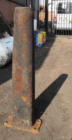
Meanwhile, when the blast pipe had been taken off the locomotive while it was being dismantled, it had been obvious that it was not in a fit condition to be put back. The picture below was taken when it was on its way to the scrap pile, and shows clearly the patch near the bottom that would turn into a hole if any attempt was made to re-use it.
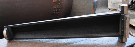
Therefore, a new blast pipe had to be made. This involved manufacturing a wooden pattern, which is shown in the picture below, and this was then taken to a foundry who made the necessary sand moulds from it, and then cast a new blast pipe in these moulds. For this purpose the outside of the pattern was used to make two half-moulds for the outside of the new blast pipe, and similarly the inside of the pattern was used to make two half-moulds for the sand core, which forms the hole up the middle of the blast pipe.
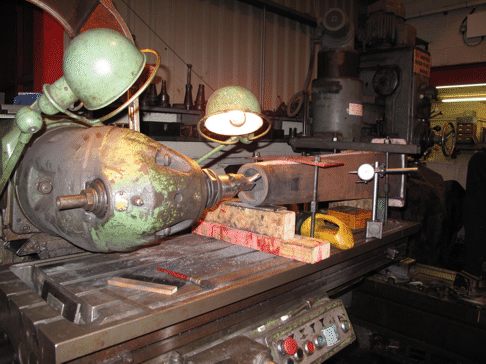
This new blast pipe then needed to be machined to fit onto the locomotive, by firstly machining flat the bottom flange and then drilling the holes in it for bolting it into place on top of the cylinder block. Then, secondly, the hole up the middle of the blast pipe, which directs the exhaust steam from the cylinders up the chimney, needed to be bored out to size. The picture below shows this being done on the milling machine.
October 2016
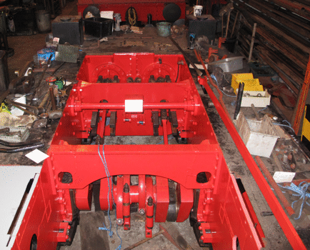
On the chassis of the locomotive the next step was to fit the brake gear. The picture shows the brake hangers and brake blocks fitted for all of the wheels, and the cross-beams which connect the pairs of brakes on each side of the locomotive. The pull-rods which apply the brakes connect these cross beams together, but in this picture they are still on the ground alongside the wheels, waiting to be fitted.
As well as the brake gear, the sanding gear needed to be fitted too. This allows the driver to drop sand under the wheels to give a better grip on the rails in wet or icy conditions. It consists of four sandboxes, two mounted in front of the front wheelset and two mounted behind the rear wheelset. Each sandbox then has a valve inside it to control the flow of sand out through a pipe attached to the bottom of the box, and these valves are connected by operating linkages to a lever in the cab.
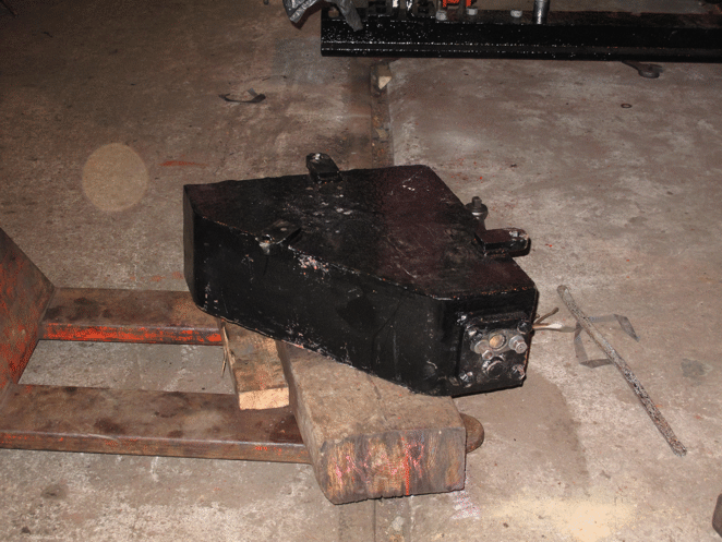
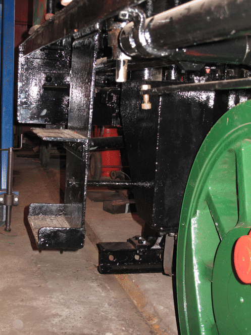
The picture below shows one of the sandboxes after it had been cleaned up and painted, waiting to be mounted onto the locomotive frames. The bottom of the box is nearest the camera, and the mounting for the sand pipe can be seen clearly: the pipe itself will be fitted after the box is in place on the frames.
The next picture then shows the rear sandbox for the right-hand side of the locomotive in place on the frames, behind the cab steps, and waiting for the operating linkages and the sand pipe to be fitted. The large pipe that is visible above the sandbox is for the vacuum brakes.
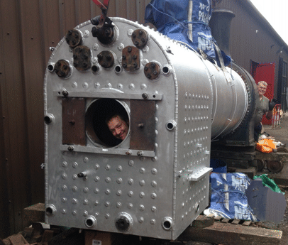
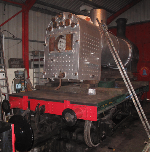
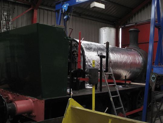
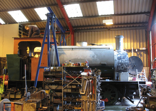
Meanwhile, the boiler had been brought into the workshop,to allow fittings to be attached to it, to prepare it for hydraulic testing. It is shown in the picture below, and is carried (very appropriately) on the restored flat-bed wagon that had originally been used at the Hunslet Engine Company's works for just this kind of job. It can be seen that the boiler drain valve has been fitted to the rear of the firebox, and also the top plate for the dome has been fitted.
As well as preparing the boiler for hydraulic testing, work is continuing on the frames, and the picture below (taken from on top of the frames at the front of the locomotive) shows the eccentric rods being fitted. These are key components of the valve gear, which controls the admission of steam to the cylinders and the release of exhaust steam up the chimney.
As will be obvious, there is not a lot of room between the frames for carrying out this kind of work!
November 2016
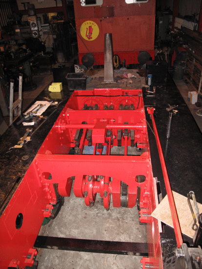
By early November fitting of the valve gear had been completed, apart from two small components, known as the die blocks, which were currently in place but needed replacing. The picture below (taken from the cab floor of the locomotive) shows all of the valve gear connected up, although the die blocks are not visible in this picture.
Below the frames, behind the rear stretcher, can be seen the rear brake cross-beam, which is still waiting for the pull-rods to be fitted. They would have been in the way of the work if they had been fitted before the valve gear was complete.
At the front end of the locomotive it can be seen that the new blast pipe has been mounted temporarily on the top of the cylinder block, to make sure that it fits correctly. It will be taken off again before the boiler is lifted back into the frames, so that it will not be in the way of this operation.
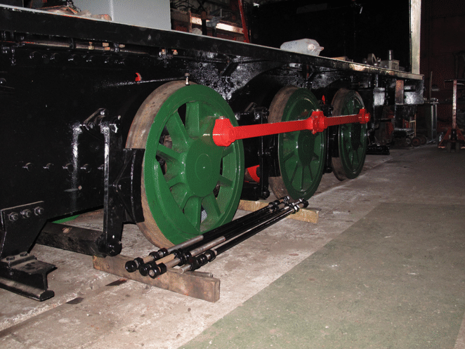
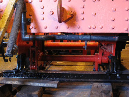
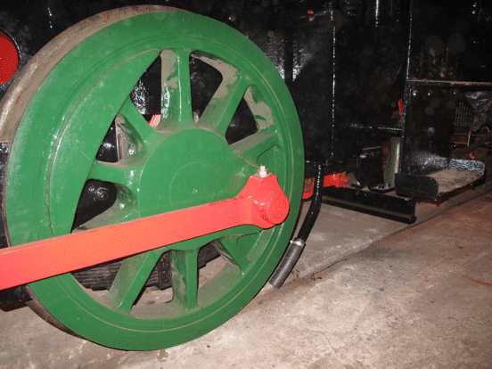
Meanwhile, the last bits of the brake gear had been fitted, including the cross-shaft which operates it all. This is shown in the picture below, which was taken from the back of the locomotive. The shaft is painted red, and the horizontal lever at the left-hand end of it is operated by the handbrake, while the vertical one at the right-hand end is operated by the steam brake cylinder. The two levers below the cross-shaft are connected to the brake pull-rods (actually painted black, although the left-hand one is reflecting the red of the frames). These run forward to the rear brake cross-beam (also painted black, although part of it is hidden by the cranks on the axle), which connects together the two brake levers and their brake blocks that are in front of the rear axle.
The big black cross-beam below all of this brake linkage is known as the derailing beam, and is firmly bolted to the frames. It is there so that if any of the wheels did come off the track (which was not an uncommon occurrence on some industrial railway systems) the locomotive would not drop down too far below the level of the rails, and so would not damage the brake gear.
December 2016
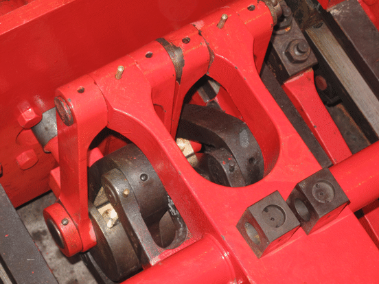
A lot of the work during December 2016 was focused on the details of preparing the boiler for hydraulic testing, but this is one of those frustrating jobs where the progress that is being made is hardly visible. One job that is visible, however, is that two new die blocks were made and fitted. The picture below shows the two old blocks sitting on top of the lifting arm for the links, with the new blocks partly visible in the links below them.
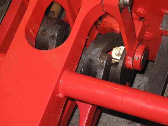
The next picture then shows a closer view of one of the new die blocks, in the right-hand link.
January 2017
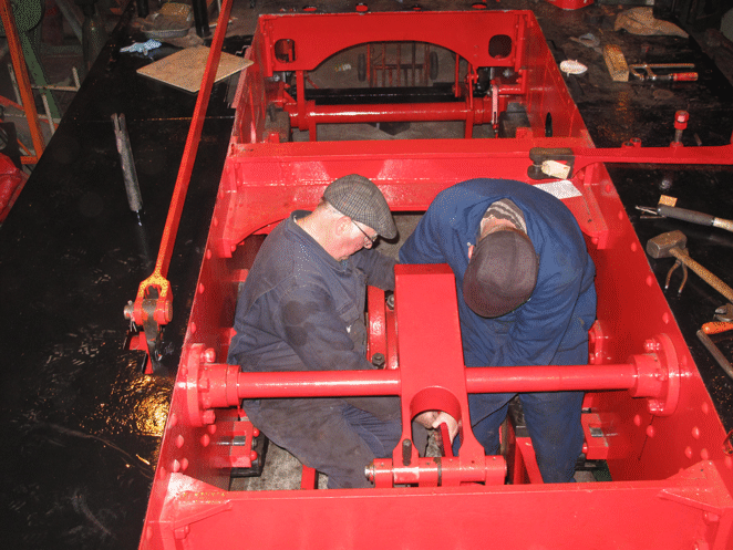
As with the previous month, a lot of the work during January 2017 was focused on continuing with the preparation of the boiler for hydraulic testing. Alongside this, though, a lot of checking had to be done of the work on the chassis, to ensure that everything had been properly finished off. One obvious bit of this work was the fitting of the sand pipes, and the picture below shows two of our volunteers carefully adjusting one of the front sand pipes to make sure that it will drop the sand on the rail, rather than either side of it.
The rear sand pipes have already been fitted, and the picture below shows the left-hand one of these complete and properly adjusted.
February 2017
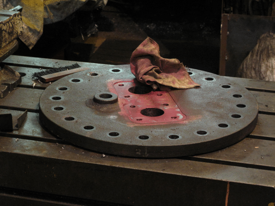
During the preparation of the boiler for hydraulic testing, a potential problem had been identified with the way in which the safety valves were mounted on the dome cover, and discussions with the boiler inspector during January had resulted in the decision that they would need to be improved. This would require the original mountings to be machined off the top of the cover, so as to produce a flat surface onto which separate mountings could be bolted. The picture below shows the dome cover after this machining had been done, and after the machined section had been coated with a red-coloured penetrating dye to check that the machining had not produced any cracks in the cover.
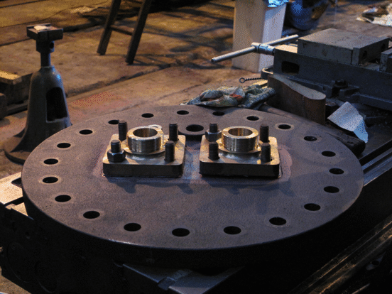
The separate mounts for the safety valves were then cast in brass and machined up, and the picture below shows them being bolted onto the dome cover.
Once these mounts had been fitted, then the dome cover was bolted into place, and everything made ready for the official hydraulic boiler test, to be conducted in the presence of the boiler inspector. This involved waiting for weather that was warm enough to conduct the test - not simply above freezing (because filling the boiler with water if there was a risk of freezing temperatures would be very likely to do it serious damage), but above 10 degrees C.
March 2017
Fortunately we did not have to wait too long, and a few warmish days at the beginning of March enabled us to run the hydraulic test, which was passed without a problem. Not only that, but we were advised by the boiler inspector that he would be happy to have the official steam test done with the boiler back in the chassis, rather than having to wait until the steam test had been done before replacing the boiler in the frames.
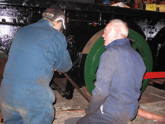
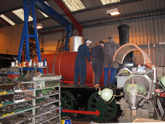
The first stage in replacing the boiler in the chassis was to lift it off the wagon, and then lower the firebox onto the new ashpan, so that this could be fitted to the bottom of it. The picture below, taken from the cab footplate on the chassis, shows the ashpan being fitted.
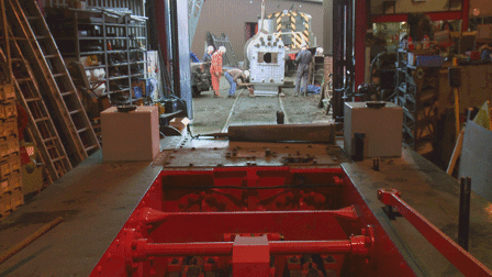
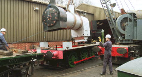
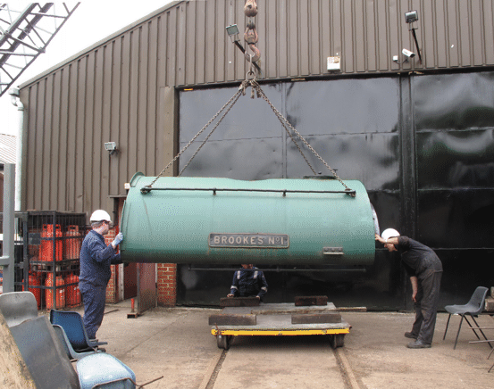
Once the ashpan had been fitted, then the whole boiler was lifted and the chassis was pulled out of the workshop, as in the picture below, and into position ready for the boiler to be lowered onto it.
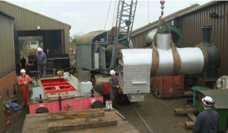
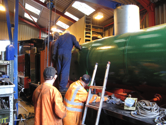
With the chassis in the right position, the boiler was swung round on the crane and positioned over the chassis ready for lowering to start, as in the picture below.
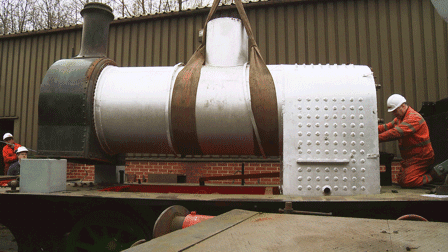
The tricky bit of the lowering was to ensure that the firebox and ashpan were fitting nicely between the frames, as they are in the picture below. Once this had been achieved then the last bit of the operation was simply to lower the boiler the rest of the way until the smokebox and the firebox mounting brackets were sitting in position on top of the frames.
With the boiler in place, the locomotive was moved back into the workshop, so that it could be prepared for steam testing.
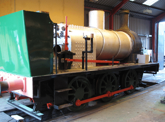
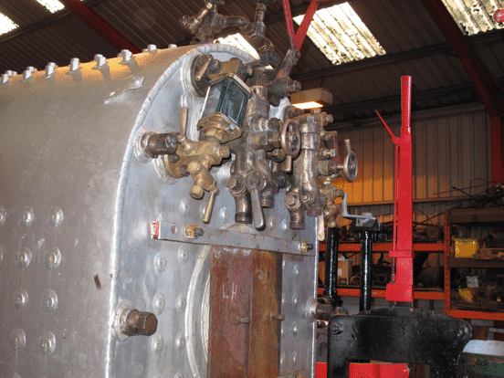
This involved attaching the various boiler fittings, and the picture below shows the boiler backhead with the water gauges and the injectors all in place. Also the steam manifold is just visible on top of the firebox.
Meanwhile, outside the workshop preparatory work on the boiler cladding sheets and the cab had begun, and the picture below shows one of the cladding sheets being sanded down, in front of the boiler of No. 6.
The cab also needed similar treatment, as in the picture below. The object next to it, under the silvery coloured cover, is the new boiler that had been built for the Sentinel. This boiler had been delivered a few days earlier, and was stored here temporarily until it could be lifted into place - but that's a separate project!
April 2017
As soon as all the fittings had been attached to the boiler, it was possible to steam test it. The locomotive was pulled outside the workshop, the boiler filled with water, and a fire lit. By about lunchtime, when the picture below was taken, we were well on the way to having full steam pressure. Once that was reached, and there were no signs of any leaks or other problems, the boiler inspector (seen in the picture watching carefully for any signs of problems) was able to declare that the boiler was fit for use. Phew!!
As soon as the boiler had cooled down the locomotive could be pushed back into the workshop, and then the boiler lagging could be fitted. This is rockwool insulation backed with aluminium foil, and the picture below shows the lagging in place.
May 2017
With the lagging in place the next step was to fix the cladding sheets, which will hold it in place. By this time these had been painted in red oxide primer, and the picture below shows them being fitted round the boiler. They were held in place temporarily with the orange webbing straps that can be seen, and then the steel boiler bands (which at this stage were still in grey undercoat) could be fastened round to fix them properly.
Meanwhile, preparations were being made for the next step, which would be to fit the saddle tank and the cab. The tank had been stored on top of a container, and so it was lifted off from there with the crane, and the picture below shows it being lowered onto a trolley, so that it could be worked on.
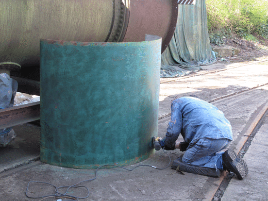
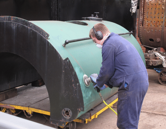
Like the cab and the cladding sheets, the tank required sanding down to prepare the surface of the metal for painting, and the picture below shows one of our volunteers doing this.
Meanwhile, work continued on painting the cladding sheets, in their final livery of Brunswick Green. This was the standard colour used by the Hunslet Engine Company if a customer did not specify a particular livery, which evidently Brookes Ltd did not when they ordered the locomotive. In the picture below the cladding sheets have been painted, and the lower front portions of the cab are being fitted, still in red oxide primer.
Once these parts had been securely bolted down to the footplate, then the top of the cab and the tank could be fitted, as in the picture below. All of a sudden, it is looking like a locomotive again - even though there is still a fair bit more work to do on it.
June 2017
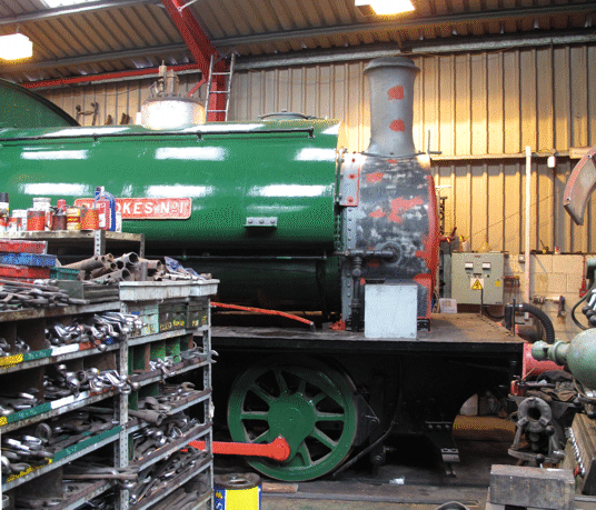
A large part of this work concerns fitting the steam piping, and also the piping for the vacuum brake system. The photograph below shows the locomotive smokebox with most of this piping now in place, so that painting the smokebox could begin.
July & August 2017
Painting continued into July, at which point a key decision had to be made: would we line out the locomotive, or leave it unlined? As far as we know it had not been lined out while it was operating at Brookes Ltd, although it did carry various other bits of decoration, including a large yellow circle on the back of the bunker which was intended to make it more easily visible. On the other hand, locomotives do look better if they are properly lined out, and so the decision was taken that we would line it out. This involved a lot of painstaking work, which ran on through the rest of July and into early August.
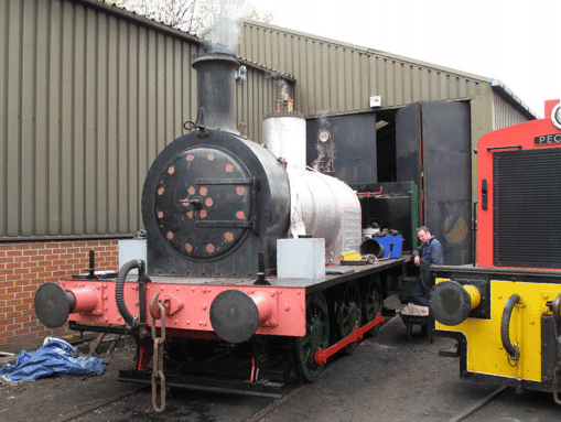
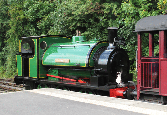
Once the paintwork was complete it was time for a test run. This was scheduled for 28th August (the Bank Holiday Monday), and so once the locomotive rostered for the services on that day (HC 1544 Slough Estates No. 3) had been prepared, Brookes No. 1 was pulled out of the workshop and lit up. For a test run steam is raised slowly, but after lunch there was enough steam pressure to decide that it would head the 2.40 train, with Slough Estates No. 3 at the rear. It ran beautifully, and the picture below shows it at Park Halt.
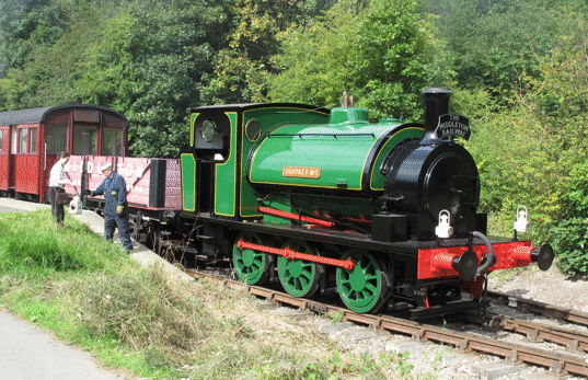
After some checks to make sure that no bearings were getting warm, the train returned to Moor Road, and it was decided that Brookes No. 1 would run the 3.20 and 4.00 trains on its own. So it did, and the picture below shows it at Park Halt, waiting to return to Moor Road with the 3.35 train.
Not surprisingly, a lot of the volunteers who had worked on it wanted to ride on it, and they were all impressed by how well it ran. "Like a sewing machine" said one; "a real Rolls Royce job" said another; while the driver's comment was "it just glided up the track".
This was not quite the end of the work, as a couple of minor points were identified that needed a little attention: a gasket had to be replaced, and there was at least one gland that needed a bit more packing immediately. But essentially the locomotive could now go into service, once crews had been trained to operate the lubricators, which are more elaborate than the ones on most of our other steam locomotives.
So the project had finished successfully. Do come and visit us to see the locomotive running.
Go back to the previous stage in this project.
Return to the overall description of this project.
More Information
Other pages about this project:
Other pages provide more information about: