


 Phase 1 finished with all the main components such as coupling rods, connecting rods, brake gear and valve gear carefully removed and stored. There was then little more that could be done until some space became available in the workshop, but this had to wait until other overhauls reached suitable points for a "grand shunt". This shunt took place in the early summer of 2014, and then phase 2 of the work could start.
Click on the links below to track our continued progress:
Autumn 2014
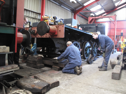
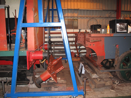
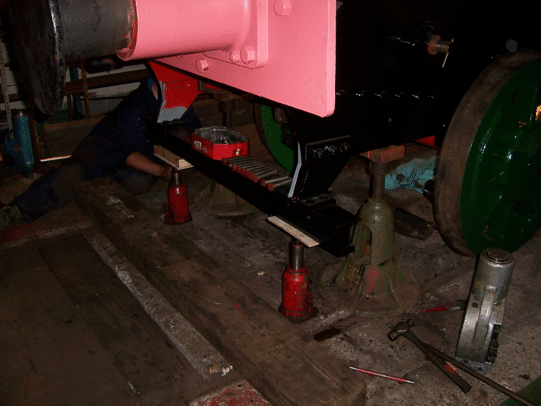
Once the frames were in the workshop, they needed to be jacked up, and carefully supported on timber packings. This was done in a series of steps, where the first step was to get to the point where the packings were carrying the weight of the frames, which allowed the springs to be removed from underneath the axleboxes. Then the remaining steps saw the frames jacked up further, until they were high enough above the rails to allow the axleboxes to be removed. Then the wheels could be rolled clear of the hornguides (the vertical pieces either side of the slots in the frames which carry the axleboxes). This gave room to start work on the long, slow and noisy job of cleaning the frames (using a needle gun) and preparing them for the first coats of paint.
Spring 2015
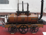
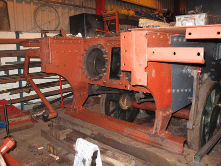
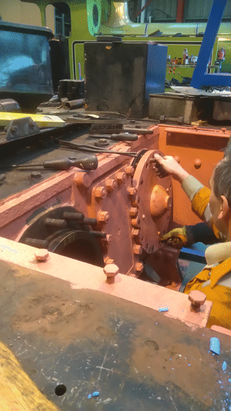
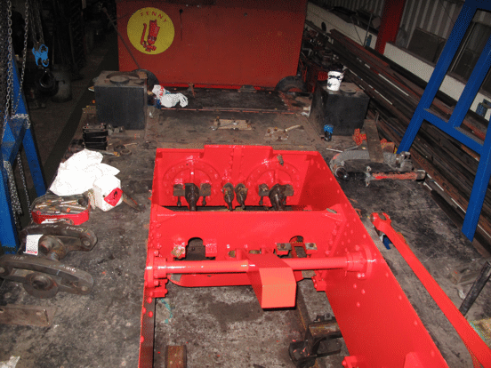
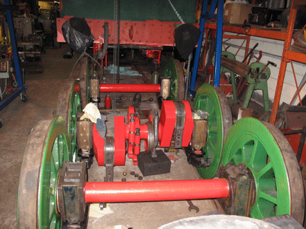
Along with preparing the frames for painting, work could start on overhauling some of the bits that had been removed from them, such as the hangers for the brakegear. As well as this, though, there were still other bits to be removed, and in particular it was necessary to take the front buffer beam off, in order to get at the cylinders and valve chests. This buffer beam is heavy enough that we would need to use the lifting gantry, but unfortunately this was just at the time where our old one (which can be seen in the background of one of the pictures above, painted red) had been condemned by the machinery inspector.
There was therefore a delay while we obtained a new gantry, but as soon as it arrived its first job was to lift the buffer beam off. With this out of the way the cylinder covers and valve chest covers could be removed, and we could start to assess what work would be needed on them.
Autumn 2015
The good news from this assessment was that we found that both the cylinders and valve chests were in sufficiently good condition that they would not need the major work that we had feared might be necessary. So, the cylinders would not need liners fitting, and the valve faces would need comparatively little resurfacing, which eliminated the other two of the three special contingencies for which we had needed to allow in planning the project.
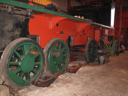
Meanwhile, the lifting gantry had been moved to the back of the frames, and had lifted them to allow the wheels to be rolled out from underneath the frames. This enabled work to start on painting the wheels and axles, and also on checking the axle bearings.
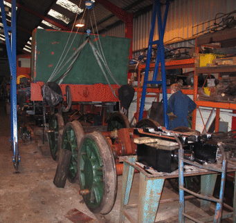
Once the wheels were out from under the frames it was also possible to start installing the jigs on the frames for measuring precisely where each axle will need to be located, so that the axleboxes could then be adjusted to provide exact positions for them.
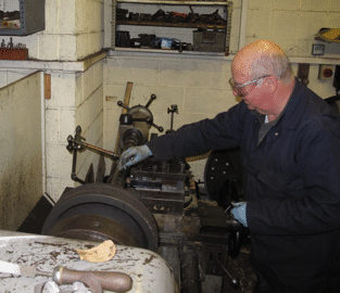
While this work was going on, since we had established that the cylinders would not need liners fitting, the pistons and piston rods could be machined to fit the cylinders as they were. This involved setting up each one in turn in the big lathe, and carefully removing just the minimum amount of metal needed to make everything true. This was the kind of job where a lot of experience was required, and it would not have been sensible to allow a younger volunteer to practice!
Winter 2015
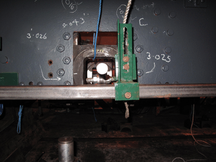
Once the jigs had been assembled onto the frames, careful measurements could be made on each axlebox, to determine exactly how much clearance would be needed at each side of each box between it and the hornguides in which it slides, so as to ensure that the distances between the axles would exactly match the side rods. Here, as the figures chalked onto the frames indicate, these measurements do really have to be made to the nearest one-thousandth of an inch. Indeed, historically part of the success of the Hunslet Engine Company had been due to them developing their technology so that they were able to build their locomotives to this level of accuracy.
Once all the measurements had been done, then each of the six axleboxes needed to be taken out of the frames, and adjusted to give the required clearances on each side. The clearances are determined by the thickness of the axlebox and the brass slipper plate which is fitted into it, and once each slipper plate has been lightly machined to give a smooth sliding surface then the clearance is adjusted by fitting shims between it and the box, before finally fixing it in place with a series of brass screws. With 12 slipper plates to adjust in this way, this required a lot of careful volunteer effort.
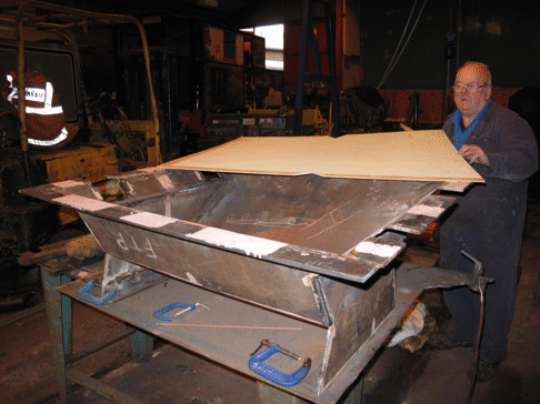
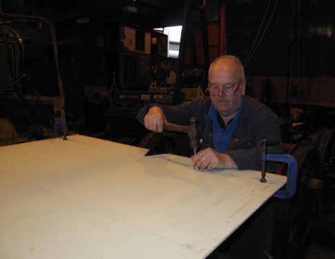
As well as this work on the frames and axleboxes, another job that had to be done was to construct a new ashpan to fit under the firebox of the boiler. Once the various parts of this had been welded together, then the top rim needed to be drilled to fit the pins underneath the firebox from which it hangs, but the only way of ensuring that the holes would be in the right places was to transfer the measurements from the firebox itself. This was done by making up a full-size template, marking this out from the firebox, and then using it to mark the ashpan itself.
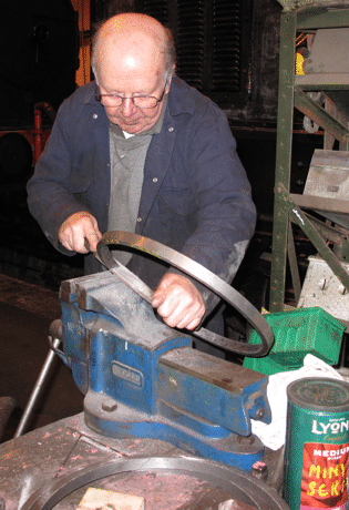
Meanwhile, for the front end of the locomotive, once the pistons and piston rods had been machined then it was necessary to make new piston rings for it. This involved making a wooden pattern that was then used to cast a circular piece of iron, like a length of tube, from which individual rings could be cut on the lathe. Each ring then needed to have a diagonal slot cut in it, be hammered gently to make the slot open up, and then filed carefully to give smooth edges to the slot. Again, this was not a task where it would have been sensible to allow a younger volunteer to practice!
Spring 2016
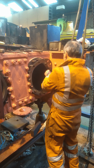
Once all of the piston rings had been made, then the pistons could be re-fitted into the cylinders and the valves into the valve chests. In the picture below the piston and piston rod have been located in the front of the right-hand cylinder, but the piston rings have not yet been fitted to it.
Meanwhile the piston and piston rod have already been fitted completely into the left-hand cylinder, and the picture below shows a gasket being fitted for the front cylinder cover.
Once the gasket fitted properly, the cylinder cover could be lifted into place (definitely a two-man job), and then fitted squarely onto the studs. The picture below shows the squareness being adjusted, and once it was correct then the cover could be tightened up.
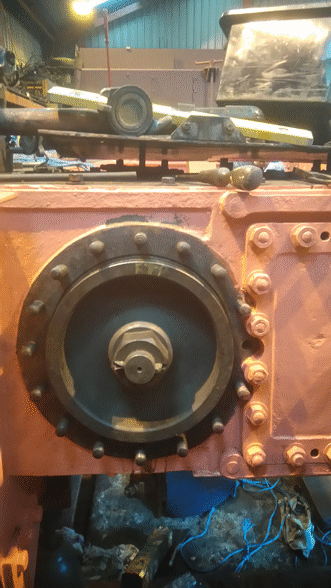
The picture below was taken shortly after this process had been completed for both cylinders, and it was taken from on top of the frames, looking towards the cylinder block. On the back of each cylinder cover can be seen the two brackets for the slidebars, with the piston rod emerging from the gland between them. Also the two valve rods can be seen emerging from their glands between the two cylinder covers. As will be very obvious, the footplating has not been painted yet!
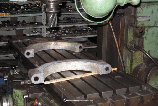
With the pistons and valves back in place, the next step was to fit the slidebars and the crossheads. The crossheads each needed to be given a coating of white metal, and this then had to be machined down so that the crossheads would be exactly the right thickness to fit between the pairs of slide bars. The same treatment was needed for the straps that fit round the eccentrics which operate the valves, and the picture below shows the two halves of one of these straps just after the white metal had been melted into place in them. They are resting on the bed of the milling machine while they cool down.
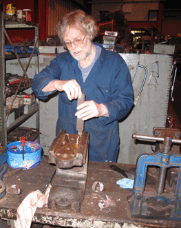
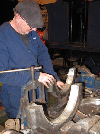
Once the two halves of each strap had cooled down, they were bolted up to form a pair, and then machining them involved two stages. The first was to mill any excess white metal off the edges of the straps, and this is being done in the picture below. The second step was then to transfer them to the lathe, and carefully machine the white metal in the inside of the straps, so that the strap would fit correctly round the eccentric.

After being machined, each of the white metal bearing surfaces had to be polished smooth, using very fine emery paper. In the picture below this is being done for the inside surface of the front part of one of the four eccentric straps: the bit of the strap that is resting on the work bench is the bracket where it is bolted to the end of the eccentric rod. In front of it on the workbench is the back part of the strap, waiting for its turn to be polished, while another strap is lying on its side on the workbench.
Meanwhile, the axleboxes had all been fitted back onto the axles, and the big end bearings had been fitted to the cranks on the middle axle, ready to have the connecting rods bolted to them. Also the two left-hand eccentric straps had been fitted to their eccentrics on this axle and painted, and in the picture below the brackets that attach them to the eccentric rods can be seen hanging down below them. As soon as the polishing shown above has been completed, then the two right-hand eccentric straps can be fitted and then painted. Then the next stage will be to roll the wheelsets in under the frames and carefully lower the frames down onto them.
Summer 2016
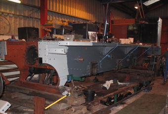
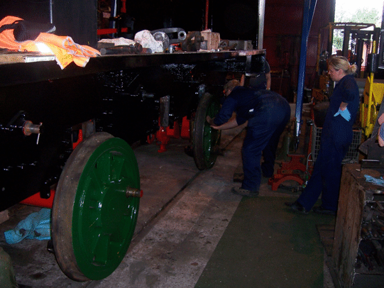
This next step happened just a couple of weeks after work started on re-tubing the boiler, which was the starting point for phase 3 of the overhaul. The lifting gantry was used to lift the rear end of the frames off their stands, and then each wheelset in turn was rolled in under the frames. In the two pictures below the front wheelset is already in position, and the middle wheelset is being rolled in.
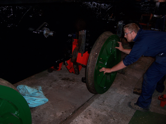
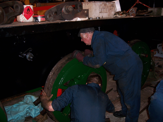
When all three wheelsets were in position, they needed to be fitted into their hornguides. For the middle wheelset this was done by lifting it up into place using the lifting gantry, and the picture below shows the wheelset being prepared for this lift.
Once this wheelset had been lifted and its axleboxes engaged in their hornguides, the pins were fitted to connect the spring hangers to the frames. Then, with this wheelset in place the front end of the frames was lowered carefully, until the front axleboxes could also be engaged into their hornguides. This is the stage that had been reached in the picture below.
The olive-green bell-shaped object under the front corner of the frames in this picture is one of the stands for the frames. We have been fortunate enough to be loaned a set of four of these, which originally belonged to Hudswell-Clarke and Co. and were used by them in their erecting shop.
Attention then shifted to the rear of the frames, and they too were lowered until the rear axleboxes could similarly be engaged. Once they were, then lowering the frames continued, one end at a time, until for each pair of axleboxes the pins could be fitted to the spring hangars, so as to connect them to the frames. The picture below shows the frames at the completion of this stage, once all of the springs had been connected to them.

Having the frames back on the wheels effectively marked the end of phase 2 of the overhaul, since the rest of the work would be concerned with re-assembling the whole of the locomotive. The first bits of this are to refit the rest of the motion work and the brake gear, but meanwhile the focus of attention shifted to the boiler, for the start of phase 3 of the overhaul.
Go on to the next stage in this project.
Go back to the previous stage in this project.
Return to the overall description of this project.
More Information
Other pages about this project:
Other pages provide more information about:
