Projects
Running Shed - The Project
A building such as this running shed is a bit like a tree, in that there is almost as much below ground that you don't see as there is visible above ground. Furthermore, all of the construction work below ground has to be done before anything visible can be erected. Not only that, but also all of the planning work has to be done before any construction at all can begin.
Project Structure
For these reasons, the overall project to build the running shed (as opposed to just raising funds for it through our "buy a brick" appeal) actually consisted of 7 phases. Some of these phases then involved several stages, and in turn some of these involved several steps, which are all described below.
1. Overall design and planning
The initial stage in this phase was to get from a rather vague "it would benefit the railway if we had a running shed" to a fairly precise "this is what we want to build, and where". As such this stage involved a lot of discussion of what we wanted and why, and making careful estimates of how much such a building might cost.
Once these had been decided, the main work in this phase was to design the building in enough detail that we could then apply to the City Council for planning permission for its construction. As part of this the costs needed to be estimated more carefully, as there would be no point in obtaining planning permission for it unless we were confident that we would then be able to afford to build it.
Making such an application actually has two stages to it. The first is what used to be called applying for outline planning permission, but is now known as a "pre-application". This stage is intended to check that a project is in principle worth submitting for full planning permission. Fortunately our pre-application did not identify any problems with the proposed building, and so very little additional design work was needed in order to progress to an application for full planning permission.
2. Construct a pit
One of the decisions made during phase 1 was that the running shed needed to have a pit between the rails. This was because preparing a locomotive for service involves the crews going underneath it, in order to check the moving parts that are between the frames of the locomotive, and also to oil up these parts. This is all much easier to do if there is a pit to work from.
Constructing this pit involved extending the existing outdoor pit, and so this had to be done before any other construction work. It also had to be completed before the detailed design work on the building could start, just in case the excavations for the pit uncovered any problems with the ground that might affect the design.
3. Detailed design and tendering
As illustrated in the page for the overall project, the building was constructed round a steel framework, with a brick dado wall for the lower parts of the walls, and with the upper parts of them and the roof being clad with coated steel sheet. For such a building a specialist firm can design and fabricate the steel framing and the cladding far more efficiently than our volunteers could. Hence, this phase of the project actually had three stages.
The first stage was that we had to prepare yet more drawings, and discuss these with the City Council to ensure that there would be no problems with obtaining Building Regulations approval when that stage was reached.
The second stage was then to put the detailed design work out to tender, based on these drawings, and then consider the tenders that were submitted by the various interested contractors for completing the design work and doing the key parts of the construction. This stage ended with a tender being accepted and a contractor appointed.
The third stage was then that the contractor had to carry out the specialised calculations that are needed to ensure that the foundations and frame of the building are strong enough (for instance, to resist loads from wind blowing on the sides or ends, or snow building up on the roof), and to complete the detailed design. They then obtained the formal Building Regulations approval from Leeds City Council, so as to ensure that when constructed the building is safe to use.
4. Construct foundations
As soon as the design of the building had been completed, and Building Regulations approval obtained, work could start on the next phase, which was the construction of the foundations. We had originally expected to do much of this work ourselves, but during the tendering process in phase 3 it became apparent that in principle it would be better if the contractors were to construct the foundations, so as to ensure that these would exactly match the frame.
As part of accepting the tenders, therefore, it was decided that the contractors should also construct the foundations. An important feature of these is that they are not just a mass of concrete, but also include steel reinforcement that must be secured together, and this all needs to be designed to provide adequate strength.
A separate stage within this phase was that an oil separator needed to be installed, to remove any oil from water draining out of the shed, and this required a hole roughly 2.8 metres (9 feet) deep. This was sufficiently deep that we certainly could not carry out this bit of the work safely with the equipment that we have. Initially it was not clear whether this would have to be done as part of constructing the foundations, but it was established that it could be designed in such a way that it did not. Consequently, separate tenders were invited from specialised contractors for doing this excavation and installing the oil separator.
5. Erect framework
As soon as the foundations were complete, then the pre-fabricated steel frame for the building could be erected on them. This was also done by the main contractor, who both supplied and erected the frame. This phase was extremely important, since all the rest of the building is supported by the frame, and it had to be constructed so that it matches exactly the foundations and the cladding sheets. Despite this, though, this phase was the shortest, and it took less than a week.
6. Roofing, cladding and brickwork
Once the steel frame was in place, then the original plan had been that work could start on fitting the cladding sheets for the walls and roof. This too was done by the main contractor, since they were also supplying the cladding sheets. In practice, though, the advice from the contractors was that once the cladding sheets for the roof had been fitted, then it would be better to lay the bricks next, and finally fit the cladding sheets for the walls to match the brickwork.
So, once they had constructed the roof, then we started laying the bricks - and there were about 9,000 of them! So, the rest of this phase was actually the part of the project that involved the most work, by quite a long way. Just how quickly we were able to progress this was one of the main things that determined when the project would be finished.
7. Fitting out
Once the walls and roof were in place, then the next step was to fit the doors, which gave us a secure building.
At this point we were able to start installing the electrical wiring needed for lighting, power supplies and ventilation. Also we were able to start installing the internal smoke troughs in the roof, which will catch and extract the smoke when eventually locomotives are being lit up in the building.
Project Timing
From previous construction projects we knew that there were all kinds of external factors which would affect how quickly we could carry out the work. A separate page describes the progress with the project, and the various delays that we encountered. We would have liked to hope that there would not be too many of these, but from previous experience we doubted that everything would really run as smoothly as that.
Thus, while we had started out hoping that it would all be finished by the end of 2016, the experience of having constructed our workshop buildings meant that we were not surprised when it actually took until almost the end of 2017 to finish it.
The keys to the good progress that we did make with this were fundraising and volunteer manpower - and that applies just as much to our other current projects, too. Please consider helping by volunteering at the railway. As the description of the work done so far makes clear, while contributing to such projects may be hard work it is also rewarding work - much more satisfying than just going to a gym for some exercise!
Go on to the next stage in this project.
Go back to the previous stage in this project.
Return to the overall description of this project.
More Information
Other pages about this project and the "Buy a Brick" appeal:
- An overview of the project and the appeal;
- The "Buy a Brick" appeal;
- The progress with the project;
- The construction of the pit;
- Design and site preparation;
- Construction of the foundations;
- Erection of the framework;
- Construction of the walls;
- Fitting out;
- The opening ceremony.
Other pages provide more information about:
Running Shed - Progress
A separate page describes the overall structure of the project to build the running shed, and in particular describes the 7 phases through which the project proceeded. This page describes how the project actually progressed, in terms of which of these phases were completed when.
1. Overall design and planning
This phase involved designing the building in enough detail that we could then apply to the City Council for planning permission for its construction. The phase started in May 2013, when we initially took the decision to go ahead with the project, on the basis of estimates that the building was likely to cost about £46,000.
This phase took much longer than we would have liked, largely because of delays in the process of obtaining planning permission. The material for the "pre-application" stage of this process, which is intended to check that a project is in principle worth submitting for full planning permission, went in to the City Council during September 2013, which unfortunately was just after all the plans for the Leeds Trolleybus system had been submitted. This meant that our project had to wait until the planners had got their heads round that lot, and so it actually took almost 10 months to be processed, whereas these pre-applications are normally supposed to be processed in about 6 weeks at most.
Once the pre-application stage had finally been completed, and we had what used to be called outline planning permission, there was very little more work that had to be done to produce the application for full planning permission. We were therefore able to submit this in August 2014, and the processing of it ran to something much closer to the expected schedule. Full planning permission was therefore received in December 2014.
2. Construct a pit
One of the decisions made during phase 1 was that the running shed needed to have a pit between the rails, which would be constructed by extending the existing outdoor pit, so that this had to be done before any other construction work. Apart from a few minor bits of work, however, we could not start this until we had received planning permission, and then for obvious safety reasons we could not go digging holes next to track on which trains were running. Consequently, the construction of this pit extension could not start until January 2015, after our Santa Special trains had finished running in December 2014.
A separate page describes in detail the work that was done for this phase, which was finally finished in early April 2015, by which time the project had cost just under £7,900.
3. Detailed design and tendering
The building is illustrated in the main project page, and for this kind of construction a specialist firm can do a far more efficient job of designing, fabricating and then assembling the steel framing and the cladding than our volunteers could. Hence, after the preparation of yet more drawings, and discussions with the City Council to ensure that there would be no problems with obtaining Building Regulations approval when that stage was reached, this detailed design work was put out to tender in November 2015.
After discussions with the interested contractors the tenders were submitted, and they were considered in January 2016, when the one from Midbrook Steel was accepted. By this time the estimated cost to complete the project had risen to just under £49,000 (as compared with the original estimate of about £46,000), and of course this is on top of what had been spent in phases 1 and 2.
In late February 2016 a contract was signed with Midbrook Steel for the construction of the foundations, the steel frame and the steel cladding. As part of this they would carry out the specialised calculations that are needed to ensure that the foundations and frame of the building will be strong enough to produce a building that will then be safe to use.
Alongside this design work, the final preparation of the running shed site needed to be done, to clear it ready for construction work in the next phase to start. Also, it had been established during the discussions with the contractors that part of the fence to the whole site would need to be removed, to allow access to the western wall of the shed. This would require a temporary closure of the footpath that runs along this side of the site, and this too has to be approved by Leeds City Council.
Eventually formal Building Regulations approval was given, as was the approval to close the footpath, and once the last bits of site preparation had been completed construction work could be scheduled to start, which tentatively was set for the end of May 2016.
4. Design and construct foundations
Having completed the design of the building, obtained both Building Regulations approval and approval to close the footpath, and prepared the site, work could start on the next phase, which is the construction of the foundations. As explained in the page describing the project structure, we had originally expected to do much of this work ourselves, and had intended to try to schedule it for the period from January to March 2016 - because again, as with the pit, it would not be safe to be digging holes next to track on which trains are running.
This plan had, however, changed during the tendering process in phase 3, since it became apparent that it would be better if the contractors were also to construct the foundations, even though this would be more expensive, because this would ensure that the foundations and the frame will match each other exactly. As part of accepting the tenders, therefore, it was decided that Midbrook Steel will also be constructing the foundations, which they could do quickly enough that it would not cause any disruption to the operation of trains.
As described above, with work on the detailed design of the frame and the foundations well under way, as was site preparation, it was hoped that the construction of the foundations could start in mid-April 2016. Unfortunately, though, the formalities involved in arranging for the temporary closure of the footpath alongside the site delayed things a bit further, and so this date slipped back, at least into May.
As well as the foundations, an oil separator needed to be installed, and (again as explained in the page describing the project structure) this would require a hole that would be sufficiently deep that we could not carry out this part of the work safely ourselves. Therefore, separate tenders were invited from specialised contractors to do this bit of the excavation and installation for us. These were received in mid-April, and Drainstore were appointed to do this work.
Finally, on Tuesday 31st May the contractors arrived to start work on the construction of the foundations. As promised they made very rapid progress, and in barely a week the foundations were complete. The work of installing the oil separator then had to be scheduled so that it would not affect our train operations, which was tricky since we had three special events between the middle of June and the middle of July: the Model Railway Exhibition, the Steampunk event and the Victorian Gala. Eventually the work was carried out during the week before the Victorian Gala (ie the week beginning Monday 11th July), and completed in good time to avoid any disruption to the gala.
5. Erect framework
As soon as the foundations had been completed and the oil separator installed, then work started on erecting the pre-fabricated steel frame for the building. This too was done by Midbrook Steel, who both supplied and erected the frame. While this phase is extremely important, because all the rest of the building is supported by the frame, it was only expected to last for a week at most, and that is just what happened. It followed on immediately from phase 4, with just the railway's Victorian Gala weekend (16th and 17th June 2016) in between, and was indeed completed within the week. It was then expected that it would run straight on into phase 6, but the contractors recommended that this plan should be changed, partly so as to fit in with the construction of the Picton shelter building.
6. Roofing, cladding and brickwork
Once the steel frame was in place, then Midbrook Steel, who were also supplying the cladding sheets, could have started work on fitting them to the frame to form the walls and roof. They fitted the roof, effectively as part of phase 5, but their recommendation was that it would be better if the brickwork of the walls were to be constructed next, before the cladding sheets were fitted above it.
Thus, the next bit of this stage was that we prepared to start laying the bricks. This sounds easy if you say it quickly, but there were at least 9,000 of them! So, we knew from experience that actually the rest of this phase would involve more work on our part than any of the rest of the project - even the construction of the pit. We tried hard to progress it as quickly as we could, but it actually ran on into early December 2016.
Once the bricks had been laid, then Midbrook returned to site, just after Christmas, and fitted the cladding sheets for the walls.
7. Fitting out
By early January 2017 the walls, doors and roof were complete enough for the building to be more-or-less secure, once the main doors had been fitted. Discussions had been going on as to whether this should be a roller shutter door or a pair of swing doors, and eventually it was decided that swing doors would be better, because a roller shutter door would have to be mounted inside the building, and so would reduce its effective length by over a foot - and this extra bit of space would make it much easier to work in the building.
So the doors were constructed, and as soon as they were fitted and the building was secure then we were able to start installing internal features. These included flooring, the electrical wiring needed for lighting, power supplies and ventilation, and also the internal smoke troughs in the roof, which will be part of the ventilation system.
We had rather hoped that a lot of this would be finished before we started running trains again in March 2017, but then we had hoped that it might be finished by the end of 2016, and from our experience of having constructed our other workshop buildings we were well aware that all sorts of delays could occur. Consequently, we were not surprised that this was not achieved, and actually the last bits of the work ended up running on almost to the end of 2017.
Go on to the next stage in this project.
Go back to the previous stage in this project.
Return to the overall description of this project.
More Information
Other pages about this project and the "Buy a Brick" appeal:
- An overview of the project and the appeal;
- The "Buy a Brick" appeal;
- The structure of the project;
- The construction of the pit;
- Design and site preparation;
- Construction of the foundations;
- Erection of the framework;
- Construction of the walls;
- Fitting out;
- The opening ceremony.
Other pages provide more information about:
Running Shed Phase 3 (Design and Site Preparation)
As described in the page for the structure of the whole project, the Running Shed is being built in seven phases. The first two phases are now complete, and have involved obtaining planning permissions and then constructing a pit between the rails that will be in the shed. This pit is now finished and the tracks have been replaced, and locomotive crews and maintenance volunteers have been taking full advantage of the increased space.
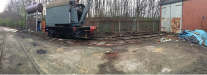
The picture below shows a panoramic view of the pit, with the crane stabled on it. Do not believe that the camera never lies - the pit and the track on which the crane is standing really are straight!
During the construction a lot of materials were used, including over 700 blocks. As illustrated in the page for the construction of the pit, all of this work, including laying all of these blocks, was completed by our volunteers, so as always a big "thank you" to them for the work that they were able to do. As well as building the pit, the feed pipe to the water tower was placed in a duct and buried, making servicing of the pipe, or even its future replacement, much easier. These works did take slightly longer to complete than we had hoped, but as is often the case with track work and civil engineering, it’s the fine tuning that takes the time to get right.
Design
Phase 3 of the project was then mainly concerned with finalising the detailed design of the Running Shed, and negotiating with the contractors who had been appointed to manufacture the steel framing of the building and the cladding sheets, and also to carry out much of the construction work. The plan and south elevation of the running shed are shown below, along with a picture of one of our locomotives standing in the location of the one shown in the elevation.
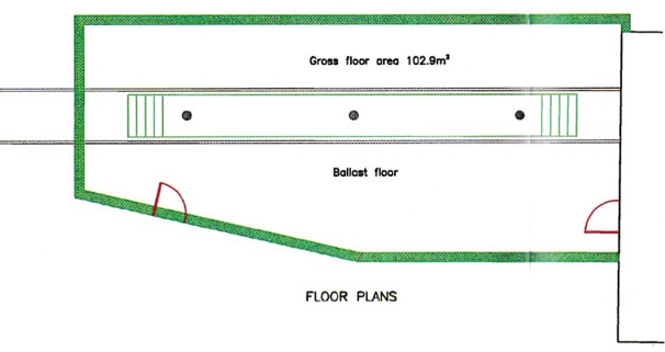
Plan of the running shed. Unlike many plans, north is to the right of this one, and south to the left.
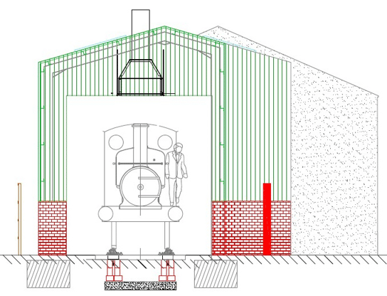
South elevation of the Running Shed (ie looking from left to right in the plan above).
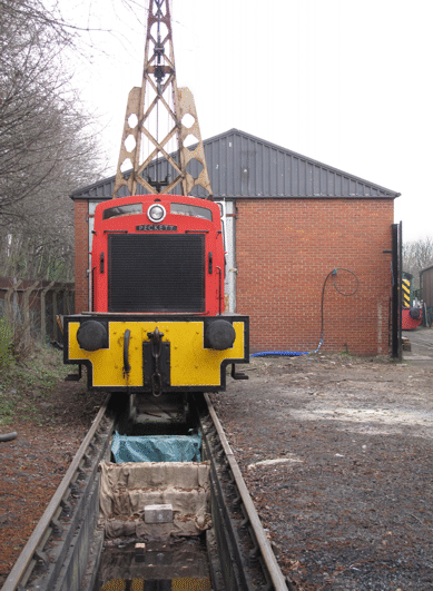
A diesel locomotive standing on the site of the Running Shed, with a crane standing behind it. They are in the same position as the steam locomotive illustrated in the elevation above.
Picture © Tony Cowling, 2016.
Site Preparation
The other main part of the work in this phase was to prepare the site ready for phase 4. During February 2016 a bit more work was done on the pit, to construct the two sets of steps that will separate the external part of the pit from the part inside the running shed.
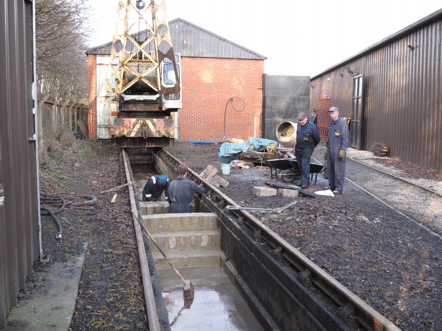
Work in progress during February 2016 on the construction of the two sets of steps that will separate the external part of the pit (nearest the camera) from the part that will be inside the running shed.
Picture © Tony Cowling, 2016.
Another part of this site preparation was that during the construction work itself the pit needed to be covered over, to avoid any risk of people working on the construction falling into it. Timber covers were therefore fabricated for this purpose, which each needed to be solid enough to support the weight of at least one person.
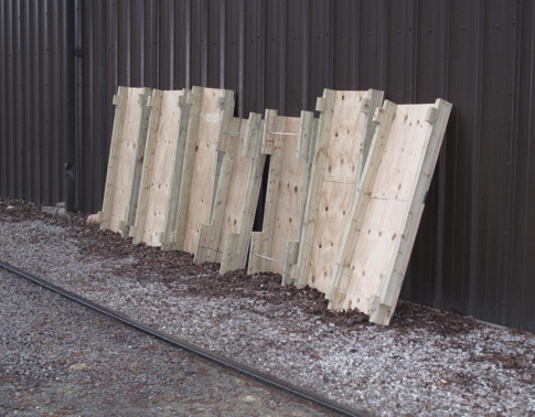
Some of the timber covers for the pit, leaning against the wall of the Engine House.
Picture © Tony Cowling, 2016.
Next Steps
The next part of the actual building work was phases 4, 5 and 6 of the project. Phase 4 consisted of excavating for and then constructing the foundations of the building, and a separate page for phase 4 describes the details of the work done for this. This phase also included installing the drainage system, and in particular an oil separator and pump. Although it is not obvious in the pictures of the pit above, it has a drainage channel set into the concrete base, which we are pleased to report works excellently, and this was connected to the oil separator when it had been installed.
As soon as the foundations were constructed then phases 5 and 6 followed immediately. Phase 5 was the erection of the steel frame for the building, which only took a week, and then phase 6 would involve the contractors fitting the steel cladding sheets to it, and our volunteers laying lots of bricks.
Go on to the next stage in this project.
Go back to the previous stage in this project.
Return to the overall description of this project.
More Information
Other pages about this project and the "Buy a Brick" appeal:
- An overview of the project and the appeal;
- The "Buy a Brick" appeal;
- The structure of the project;
- The progress with the project;
- The construction of the pit;
- Construction of the foundations;
- Erection of the framework;
- Construction of the walls;
- Fitting out;
- The opening ceremony.
Other pages provide more information about:
"Brookes No. 1" Overhaul Phase 2
 Phase 1 finished with all the main components such as coupling rods, connecting rods, brake gear and valve gear carefully removed and stored. There was then little more that could be done until some space became available in the workshop, but this had to wait until other overhauls reached suitable points for a "grand shunt". This shunt took place in the early summer of 2014, and then phase 2 of the work could start.
Click on the links below to track our continued progress:
Autumn 2014
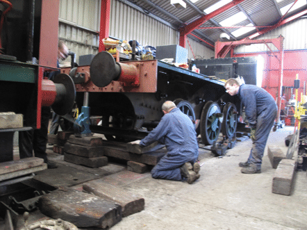
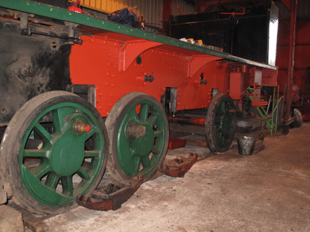
Once the frames were in the workshop, they needed to be jacked up, and carefully supported on timber packings. This was done in a series of steps, where the first step was to get to the point where the packings were carrying the weight of the frames, which allowed the springs to be removed from underneath the axleboxes. Then the remaining steps saw the frames jacked up further, until they were high enough above the rails to allow the axleboxes to be removed. Then the wheels could be rolled clear of the hornguides (the vertical pieces either side of the slots in the frames which carry the axleboxes). This gave room to start work on the long, slow and noisy job of cleaning the frames (using a needle gun) and preparing them for the first coats of paint.
Spring 2015
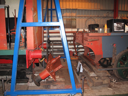
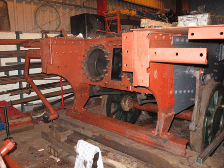
Along with preparing the frames for painting, work could start on overhauling some of the bits that had been removed from them, such as the hangers for the brakegear. As well as this, though, there were still other bits to be removed, and in particular it was necessary to take the front buffer beam off, in order to get at the cylinders and valve chests. This buffer beam is heavy enough that we would need to use the lifting gantry, but unfortunately this was just at the time where our old one (which can be seen in the background of one of the pictures above, painted red) had been condemned by the machinery inspector.
There was therefore a delay while we obtained a new gantry, but as soon as it arrived its first job was to lift the buffer beam off. With this out of the way the cylinder covers and valve chest covers could be removed, and we could start to assess what work would be needed on them.
Autumn 2015
The good news from this assessment was that we found that both the cylinders and valve chests were in sufficiently good condition that they would not need the major work that we had feared might be necessary. So, the cylinders would not need liners fitting, and the valve faces would need comparatively little resurfacing, which eliminated the other two of the three special contingencies for which we had needed to allow in planning the project.
Meanwhile, the lifting gantry had been moved to the back of the frames, and had lifted them to allow the wheels to be rolled out from underneath the frames. This enabled work to start on painting the wheels and axles, and also on checking the axle bearings.
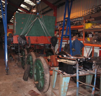
Once the wheels were out from under the frames it was also possible to start installing the jigs on the frames for measuring precisely where each axle will need to be located, so that the axleboxes could then be adjusted to provide exact positions for them.
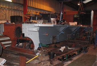
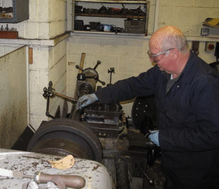
While this work was going on, since we had established that the cylinders would not need liners fitting, the pistons and piston rods could be machined to fit the cylinders as they were. This involved setting up each one in turn in the big lathe, and carefully removing just the minimum amount of metal needed to make everything true. This was the kind of job where a lot of experience was required, and it would not have been sensible to allow a younger volunteer to practice!
Winter 2015
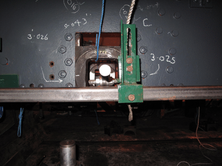
Once the jigs had been assembled onto the frames, careful measurements could be made on each axlebox, to determine exactly how much clearance would be needed at each side of each box between it and the hornguides in which it slides, so as to ensure that the distances between the axles would exactly match the side rods. Here, as the figures chalked onto the frames indicate, these measurements do really have to be made to the nearest one-thousandth of an inch. Indeed, historically part of the success of the Hunslet Engine Company had been due to them developing their technology so that they were able to build their locomotives to this level of accuracy.
Once all the measurements had been done, then each of the six axleboxes needed to be taken out of the frames, and adjusted to give the required clearances on each side. The clearances are determined by the thickness of the axlebox and the brass slipper plate which is fitted into it, and once each slipper plate has been lightly machined to give a smooth sliding surface then the clearance is adjusted by fitting shims between it and the box, before finally fixing it in place with a series of brass screws. With 12 slipper plates to adjust in this way, this required a lot of careful volunteer effort.
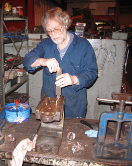
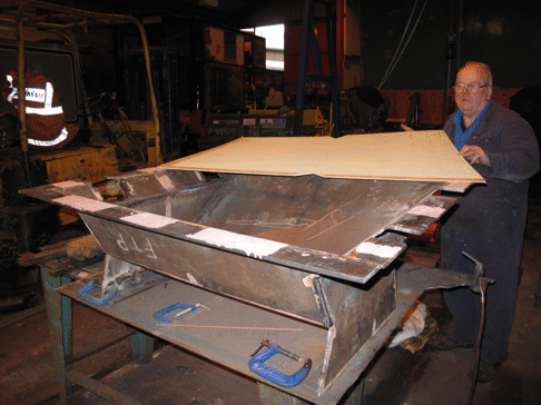
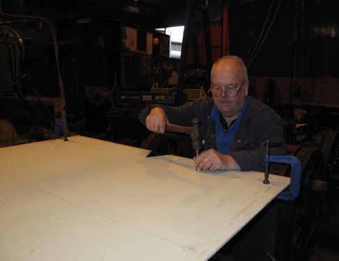
As well as this work on the frames and axleboxes, another job that had to be done was to construct a new ashpan to fit under the firebox of the boiler. Once the various parts of this had been welded together, then the top rim needed to be drilled to fit the pins underneath the firebox from which it hangs, but the only way of ensuring that the holes would be in the right places was to transfer the measurements from the firebox itself. This was done by making up a full-size template, marking this out from the firebox, and then using it to mark the ashpan itself.
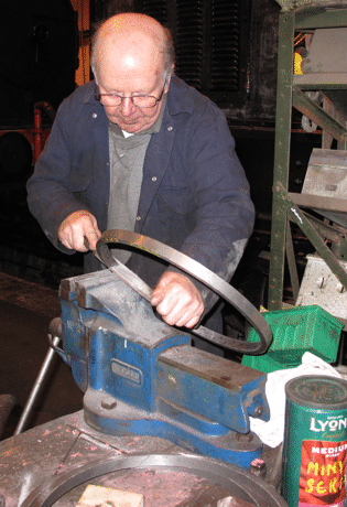
Meanwhile, for the front end of the locomotive, once the pistons and piston rods had been machined then it was necessary to make new piston rings for it. This involved making a wooden pattern that was then used to cast a circular piece of iron, like a length of tube, from which individual rings could be cut on the lathe. Each ring then needed to have a diagonal slot cut in it, be hammered gently to make the slot open up, and then filed carefully to give smooth edges to the slot. Again, this was not a task where it would have been sensible to allow a younger volunteer to practice!
Spring 2016
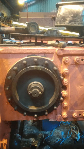
Once all of the piston rings had been made, then the pistons could be re-fitted into the cylinders and the valves into the valve chests. In the picture below the piston and piston rod have been located in the front of the right-hand cylinder, but the piston rings have not yet been fitted to it.
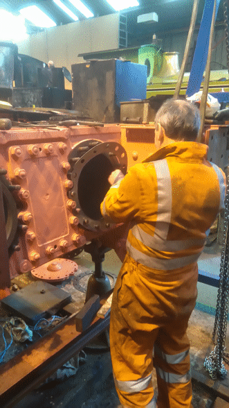
Meanwhile the piston and piston rod have already been fitted completely into the left-hand cylinder, and the picture below shows a gasket being fitted for the front cylinder cover.
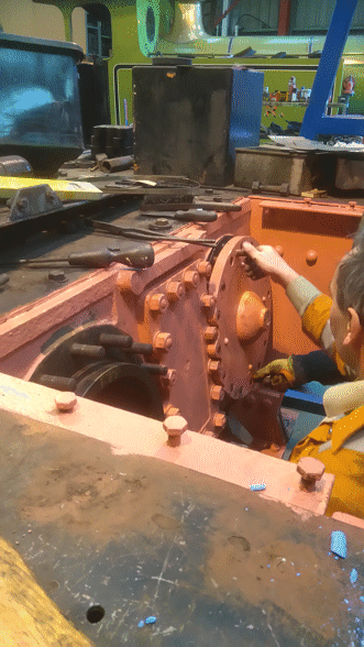
Once the gasket fitted properly, the cylinder cover could be lifted into place (definitely a two-man job), and then fitted squarely onto the studs. The picture below shows the squareness being adjusted, and once it was correct then the cover could be tightened up.
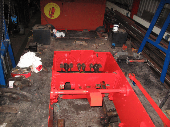
The picture below was taken shortly after this process had been completed for both cylinders, and it was taken from on top of the frames, looking towards the cylinder block. On the back of each cylinder cover can be seen the two brackets for the slidebars, with the piston rod emerging from the gland between them. Also the two valve rods can be seen emerging from their glands between the two cylinder covers. As will be very obvious, the footplating has not been painted yet!
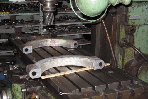
With the pistons and valves back in place, the next step was to fit the slidebars and the crossheads. The crossheads each needed to be given a coating of white metal, and this then had to be machined down so that the crossheads would be exactly the right thickness to fit between the pairs of slide bars. The same treatment was needed for the straps that fit round the eccentrics which operate the valves, and the picture below shows the two halves of one of these straps just after the white metal had been melted into place in them. They are resting on the bed of the milling machine while they cool down.
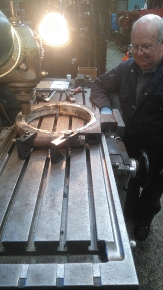
Once the two halves of each strap had cooled down, they were bolted up to form a pair, and then machining them involved two stages. The first was to mill any excess white metal off the edges of the straps, and this is being done in the picture below. The second step was then to transfer them to the lathe, and carefully machine the white metal in the inside of the straps, so that the strap would fit correctly round the eccentric.
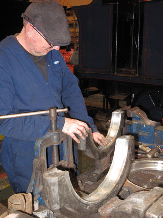
After being machined, each of the white metal bearing surfaces had to be polished smooth, using very fine emery paper. In the picture below this is being done for the inside surface of the front part of one of the four eccentric straps: the bit of the strap that is resting on the work bench is the bracket where it is bolted to the end of the eccentric rod. In front of it on the workbench is the back part of the strap, waiting for its turn to be polished, while another strap is lying on its side on the workbench.
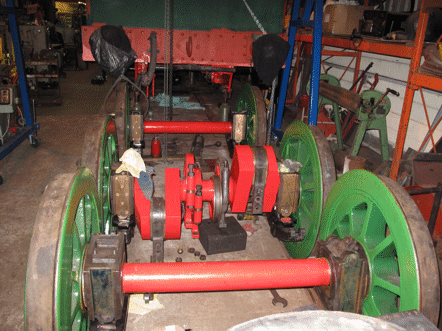
Meanwhile, the axleboxes had all been fitted back onto the axles, and the big end bearings had been fitted to the cranks on the middle axle, ready to have the connecting rods bolted to them. Also the two left-hand eccentric straps had been fitted to their eccentrics on this axle and painted, and in the picture below the brackets that attach them to the eccentric rods can be seen hanging down below them. As soon as the polishing shown above has been completed, then the two right-hand eccentric straps can be fitted and then painted. Then the next stage will be to roll the wheelsets in under the frames and carefully lower the frames down onto them.
Summer 2016
This next step happened just a couple of weeks after work started on re-tubing the boiler, which was the starting point for phase 3 of the overhaul. The lifting gantry was used to lift the rear end of the frames off their stands, and then each wheelset in turn was rolled in under the frames. In the two pictures below the front wheelset is already in position, and the middle wheelset is being rolled in.
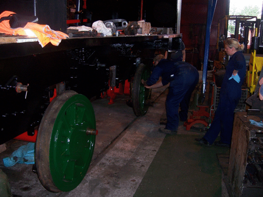
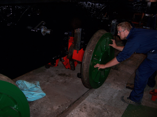
When all three wheelsets were in position, they needed to be fitted into their hornguides. For the middle wheelset this was done by lifting it up into place using the lifting gantry, and the picture below shows the wheelset being prepared for this lift.
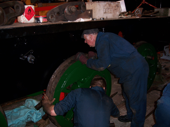
Once this wheelset had been lifted and its axleboxes engaged in their hornguides, the pins were fitted to connect the spring hangers to the frames. Then, with this wheelset in place the front end of the frames was lowered carefully, until the front axleboxes could also be engaged into their hornguides. This is the stage that had been reached in the picture below.
The olive-green bell-shaped object under the front corner of the frames in this picture is one of the stands for the frames. We have been fortunate enough to be loaned a set of four of these, which originally belonged to Hudswell-Clarke and Co. and were used by them in their erecting shop.
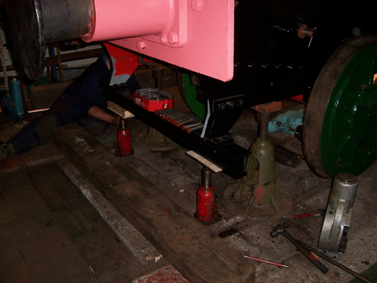
Attention then shifted to the rear of the frames, and they too were lowered until the rear axleboxes could similarly be engaged. Once they were, then lowering the frames continued, one end at a time, until for each pair of axleboxes the pins could be fitted to the spring hangars, so as to connect them to the frames. The picture below shows the frames at the completion of this stage, once all of the springs had been connected to them.
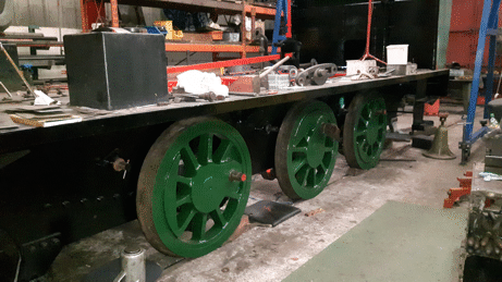
Having the frames back on the wheels effectively marked the end of phase 2 of the overhaul, since the rest of the work would be concerned with re-assembling the whole of the locomotive. The first bits of this are to refit the rest of the motion work and the brake gear, but meanwhile the focus of attention shifted to the boiler, for the start of phase 3 of the overhaul.
Go on to the next stage in this project.
Go back to the previous stage in this project.
Return to the overall description of this project.
More Information
Other pages about this project:
Other pages provide more information about:
Running Shed Phase 2 (The Pit)
As described in the page for the structure of the whole project, the Running Shed is being built in seven phases. The first of these was to obtain the necessary planning permission, and the the second involved constructing a pit that eventually would be between the rails in the shed. This was needed to allow easy access to the working parts between the frames of the locomotives, either when preparing them for service or when carrying out maintenance work on them.
We already had such a pit in the track outside where the running shed was to go, and so constructing this new pit actually just involved extending the existing one at both ends. This was all done during the first few months of 2015, and the first stage in it was to lift the track from the existing pit. This was done at the very beginning of January 2015, and then (undeterred by the weather) excavation work started on 15th January.
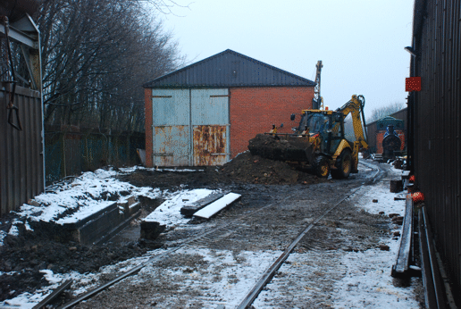
Excavation of the running shed pit in progress - it had been snowing earlier in the day, but this had stopped (just!) by the time that this picture was taken. The walls of the existing pit can be seen to the left of the picture, between the two excavated areas.
Picture © Andrew Gill, 2015.
Once the holes had been excavated, they needed to be prepared for laying the concrete base of the pit. This involved constructing wooden "shuttering" to contain the concrete at each side, and putting down a layer of sand (known as a "blinding") on top of special geo-textile (which stops mud coming up through the sand). The sand then had to be rolled firm, and steel mesh cut to shape to reinforce the concrete.
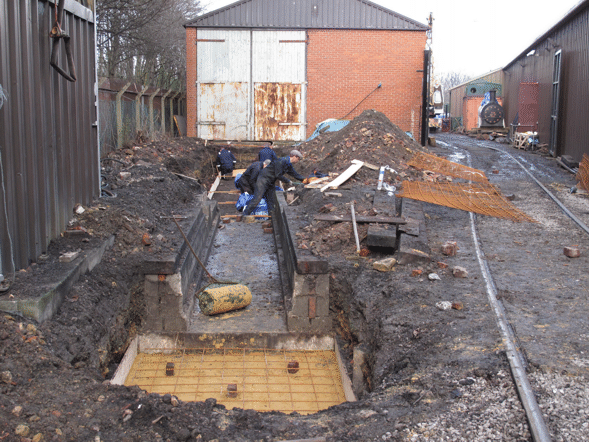
Preparing for the base of the extended pit, on 31st January. The shuttering, sand blinding and reinforcement for the southern part are in the foreground (as is the roller for the sand), and in the background the shuttering for the running shed pit is being constructed.
Picture © Tony Cowling, 2015.
Once all this preparation was complete, then the concrete could be laid, which was done on 7th February.
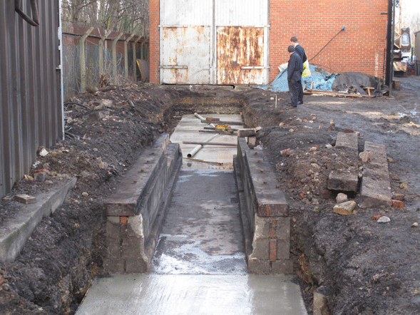
This shows the concrete base of the pit just after it had been laid. The two pieces of pipe in the background are acting as moulds, to produce drainage channels in the surface of the concrete.
Picture © Tony Cowling, 2015.
After a few days to allow the concrete of the base to cure, work could start on laying the concrete blocks that form the walls of the pit. Like the walls of the existing pit that can be seen in the picture above, each side of the pit consists of a base course of pairs of blocks laid on their sides, and then two courses on top of the base ones to form two parallel walls with a cavity between them. This cavity is then filled with concrete.
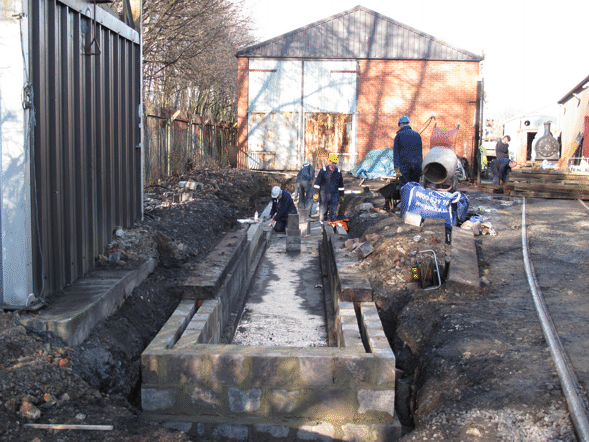
By 21st February the concrete blockwork for the south end of the pit had been constructed, and work was in progress on laying the base course of blocks for the running shed pit.
Picture © Tony Cowling, 2015.
Once the cavity between the walls had been filled with concrete, and this had cured, then the timbers that support the track on top of the walls were set in place and the chairs to hold the rails screwed down temporarily to them.
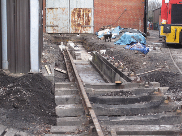
By 28th February the timbers for the south end of the pit were in place, concrete sleepers had been laid to connect the pit to the rest of the track, and one rail had been partly laid. The blocks lined up in the background are ready to be laid for the walls of the running shed pit.
Picture © Tony Cowling, 2015.
Laying the blockwork was the longest part of the job, and so while it was progressing on the part of the pit that would be in the running shed, work was also going on to complete the southern end of the pit, so that this would be available for use.
Once the timbers to support the track had been laid, and a lot of careful measuring done to make sure that the rails would be to the correct gauge (ie exactly the right distance apart) when they were put into the chairs, holes were drilled down through the timbers into the concrete, and bolts fixed into these holes in the concrete with resin adhesive. Once the adhesive had cured, then nuts could be screwed down onto the bolts to hold the timbers securely, and the chairs could be screwed down permanently onto the timbers.
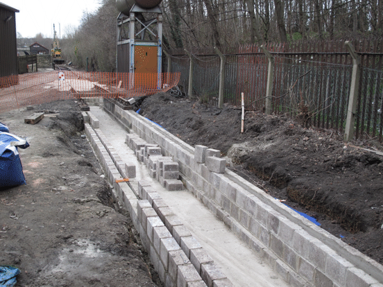
By 21st March the southern end of the pit had been completed and was available for use for preparing locomotives for service. The blockwork for the western wall of the pit was complete, and good progress had been made on the eastern wall. The blue piping that can be seen carries the supply to the water tower that is opposite the far end of the pit.
Picture © Tony Cowling, 2015.
Once all of the blockwork had been completed, then the timbers for the northern part of the pit could be laid on top of it, and the track work could be completed to connect up again with the track inside the existing workshop. This was finished in April 2015, and marked the end of phase 2 of the project.
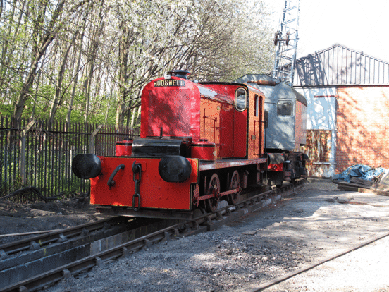
By early April the pit was complete, and HC D577 Mary is stabled on top of it, along with one of our cranes.
Picture © Tony Cowling, 2015.
For the next stages of the work, see other pages for this project.
Go on to the next stage in this project.
Go back to the previous stage in this project.
Return to the overall description of this project.
More Information
Other pages about this project and the "Buy a Brick" appeal:
- An overview of the project and the appeal;
- The "Buy a Brick" appeal;
- The structure of the project;
- The progress with the project;
- Design and site preparation;
- Construction of the foundations;
- Erection of the framework;
- Construction of the walls;
- Fitting out;
- The opening ceremony.
Other pages provide more information about:

