General
Running Shed Phase 3 (Design and Site Preparation)
As described in the page for the structure of the whole project, the Running Shed is being built in seven phases. The first two phases are now complete, and have involved obtaining planning permissions and then constructing a pit between the rails that will be in the shed. This pit is now finished and the tracks have been replaced, and locomotive crews and maintenance volunteers have been taking full advantage of the increased space.
The picture below shows a panoramic view of the pit, with the crane stabled on it. Do not believe that the camera never lies - the pit and the track on which the crane is standing really are straight!
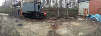
During the construction a lot of materials were used, including over 700 blocks. As illustrated in the page for the construction of the pit, all of this work, including laying all of these blocks, was completed by our volunteers, so as always a big "thank you" to them for the work that they were able to do. As well as building the pit, the feed pipe to the water tower was placed in a duct and buried, making servicing of the pipe, or even its future replacement, much easier. These works did take slightly longer to complete than we had hoped, but as is often the case with track work and civil engineering, it’s the fine tuning that takes the time to get right.
Design
Phase 3 of the project was then mainly concerned with finalising the detailed design of the Running Shed, and negotiating with the contractors who had been appointed to manufacture the steel framing of the building and the cladding sheets, and also to carry out much of the construction work. The plan and south elevation of the running shed are shown below, along with a picture of one of our locomotives standing in the location of the one shown in the elevation.
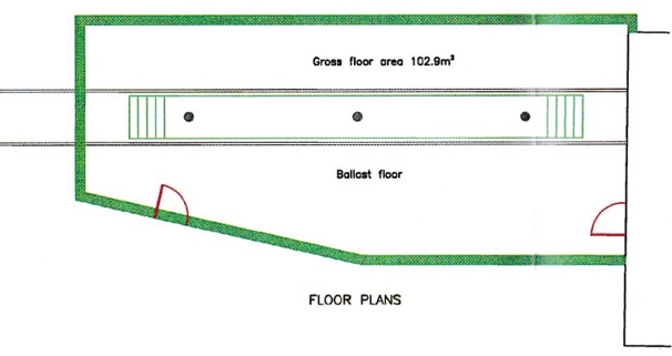
Plan of the running shed. Unlike many plans, north is to the right of this one, and south to the left.
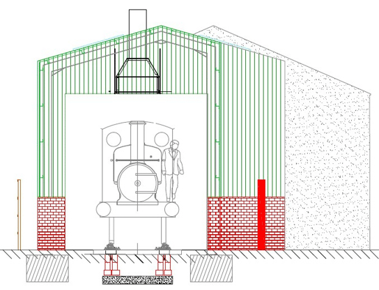
South elevation of the Running Shed (ie looking from left to right in the plan above).
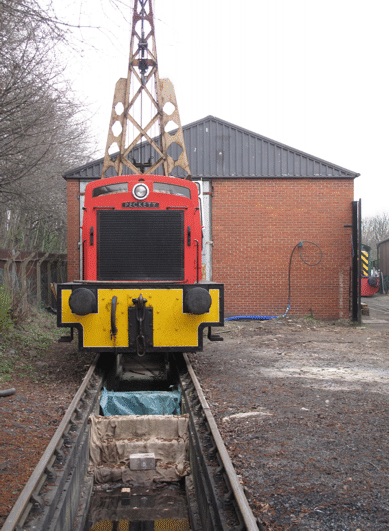
A diesel locomotive standing on the site of the Running Shed, with a crane standing behind it. They are in the same position as the steam locomotive illustrated in the elevation above.
Picture © Tony Cowling, 2016.
Site Preparation
The other main part of the work in this phase was to prepare the site ready for phase 4. During February 2016 a bit more work was done on the pit, to construct the two sets of steps that will separate the external part of the pit from the part inside the running shed.
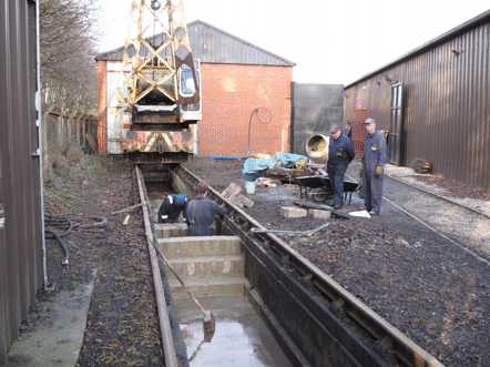
Work in progress during February 2016 on the construction of the two sets of steps that will separate the external part of the pit (nearest the camera) from the part that will be inside the running shed.
Picture © Tony Cowling, 2016.
Another part of this site preparation was that during the construction work itself the pit needed to be covered over, to avoid any risk of people working on the construction falling into it. Timber covers were therefore fabricated for this purpose, which each needed to be solid enough to support the weight of at least one person.
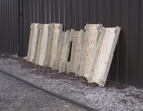
Some of the timber covers for the pit, leaning against the wall of the Engine House.
Picture © Tony Cowling, 2016.
Next Steps
The next part of the actual building work was phases 4, 5 and 6 of the project. Phase 4 consisted of excavating for and then constructing the foundations of the building, and a separate page for phase 4 describes the details of the work done for this. This phase also included installing the drainage system, and in particular an oil separator and pump. Although it is not obvious in the pictures of the pit above, it has a drainage channel set into the concrete base, which we are pleased to report works excellently, and this was connected to the oil separator when it had been installed.
As soon as the foundations were constructed then phases 5 and 6 followed immediately. Phase 5 was the erection of the steel frame for the building, which only took a week, and then phase 6 would involve the contractors fitting the steel cladding sheets to it, and our volunteers laying lots of bricks.
Go on to the next stage in this project.
Go back to the previous stage in this project.
Return to the overall description of this project.
More Information
Other pages about this project and the "Buy a Brick" appeal:
- An overview of the project and the appeal;
- The "Buy a Brick" appeal;
- The structure of the project;
- The progress with the project;
- The construction of the pit;
- Construction of the foundations;
- Erection of the framework;
- Construction of the walls;
- Fitting out;
- The opening ceremony.
Other pages provide more information about:
"Brookes No. 1" Overhaul Phase 2
 Phase 1 finished with all the main components such as coupling rods, connecting rods, brake gear and valve gear carefully removed and stored. There was then little more that could be done until some space became available in the workshop, but this had to wait until other overhauls reached suitable points for a "grand shunt". This shunt took place in the early summer of 2014, and then phase 2 of the work could start.
Click on the links below to track our continued progress:
Autumn 2014
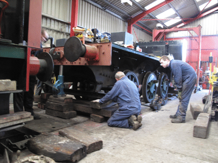
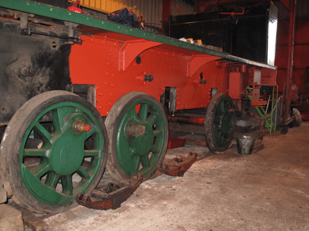
Once the frames were in the workshop, they needed to be jacked up, and carefully supported on timber packings. This was done in a series of steps, where the first step was to get to the point where the packings were carrying the weight of the frames, which allowed the springs to be removed from underneath the axleboxes. Then the remaining steps saw the frames jacked up further, until they were high enough above the rails to allow the axleboxes to be removed. Then the wheels could be rolled clear of the hornguides (the vertical pieces either side of the slots in the frames which carry the axleboxes). This gave room to start work on the long, slow and noisy job of cleaning the frames (using a needle gun) and preparing them for the first coats of paint.
Spring 2015
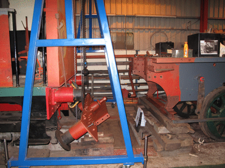
Along with preparing the frames for painting, work could start on overhauling some of the bits that had been removed from them, such as the hangers for the brakegear. As well as this, though, there were still other bits to be removed, and in particular it was necessary to take the front buffer beam off, in order to get at the cylinders and valve chests. This buffer beam is heavy enough that we would need to use the lifting gantry, but unfortunately this was just at the time where our old one (which can be seen in the background of one of the pictures above, painted red) had been condemned by the machinery inspector.
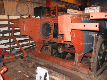
There was therefore a delay while we obtained a new gantry, but as soon as it arrived its first job was to lift the buffer beam off. With this out of the way the cylinder covers and valve chest covers could be removed, and we could start to assess what work would be needed on them.
Autumn 2015
The good news from this assessment was that we found that both the cylinders and valve chests were in sufficiently good condition that they would not need the major work that we had feared might be necessary. So, the cylinders would not need liners fitting, and the valve faces would need comparatively little resurfacing, which eliminated the other two of the three special contingencies for which we had needed to allow in planning the project.
Meanwhile, the lifting gantry had been moved to the back of the frames, and had lifted them to allow the wheels to be rolled out from underneath the frames. This enabled work to start on painting the wheels and axles, and also on checking the axle bearings.
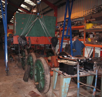
Once the wheels were out from under the frames it was also possible to start installing the jigs on the frames for measuring precisely where each axle will need to be located, so that the axleboxes could then be adjusted to provide exact positions for them.
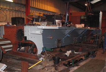
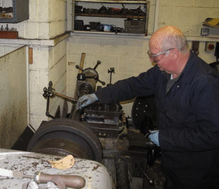
While this work was going on, since we had established that the cylinders would not need liners fitting, the pistons and piston rods could be machined to fit the cylinders as they were. This involved setting up each one in turn in the big lathe, and carefully removing just the minimum amount of metal needed to make everything true. This was the kind of job where a lot of experience was required, and it would not have been sensible to allow a younger volunteer to practice!
Winter 2015
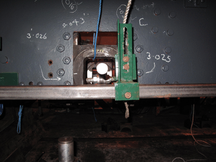
Once the jigs had been assembled onto the frames, careful measurements could be made on each axlebox, to determine exactly how much clearance would be needed at each side of each box between it and the hornguides in which it slides, so as to ensure that the distances between the axles would exactly match the side rods. Here, as the figures chalked onto the frames indicate, these measurements do really have to be made to the nearest one-thousandth of an inch. Indeed, historically part of the success of the Hunslet Engine Company had been due to them developing their technology so that they were able to build their locomotives to this level of accuracy.
Once all the measurements had been done, then each of the six axleboxes needed to be taken out of the frames, and adjusted to give the required clearances on each side. The clearances are determined by the thickness of the axlebox and the brass slipper plate which is fitted into it, and once each slipper plate has been lightly machined to give a smooth sliding surface then the clearance is adjusted by fitting shims between it and the box, before finally fixing it in place with a series of brass screws. With 12 slipper plates to adjust in this way, this required a lot of careful volunteer effort.
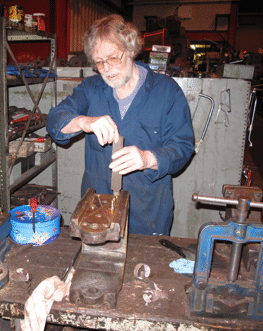
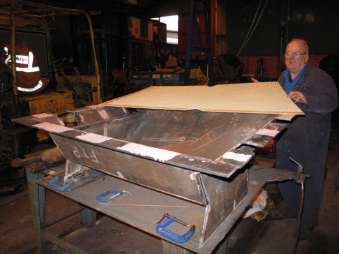
As well as this work on the frames and axleboxes, another job that had to be done was to construct a new ashpan to fit under the firebox of the boiler. Once the various parts of this had been welded together, then the top rim needed to be drilled to fit the pins underneath the firebox from which it hangs, but the only way of ensuring that the holes would be in the right places was to transfer the measurements from the firebox itself. This was done by making up a full-size template, marking this out from the firebox, and then using it to mark the ashpan itself.
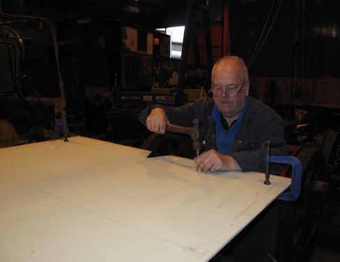
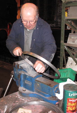
Meanwhile, for the front end of the locomotive, once the pistons and piston rods had been machined then it was necessary to make new piston rings for it. This involved making a wooden pattern that was then used to cast a circular piece of iron, like a length of tube, from which individual rings could be cut on the lathe. Each ring then needed to have a diagonal slot cut in it, be hammered gently to make the slot open up, and then filed carefully to give smooth edges to the slot. Again, this was not a task where it would have been sensible to allow a younger volunteer to practice!
Spring 2016
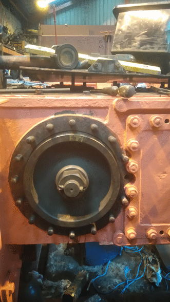
Once all of the piston rings had been made, then the pistons could be re-fitted into the cylinders and the valves into the valve chests. In the picture below the piston and piston rod have been located in the front of the right-hand cylinder, but the piston rings have not yet been fitted to it.
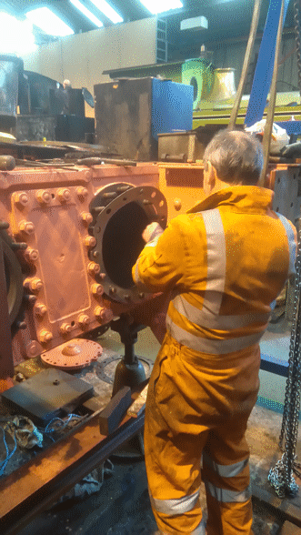
Meanwhile the piston and piston rod have already been fitted completely into the left-hand cylinder, and the picture below shows a gasket being fitted for the front cylinder cover.
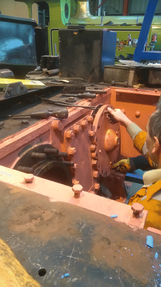
Once the gasket fitted properly, the cylinder cover could be lifted into place (definitely a two-man job), and then fitted squarely onto the studs. The picture below shows the squareness being adjusted, and once it was correct then the cover could be tightened up.
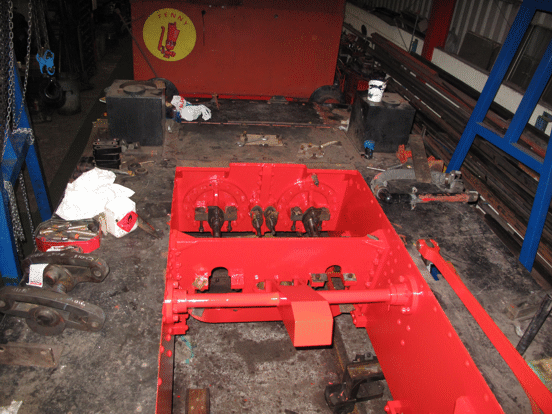
The picture below was taken shortly after this process had been completed for both cylinders, and it was taken from on top of the frames, looking towards the cylinder block. On the back of each cylinder cover can be seen the two brackets for the slidebars, with the piston rod emerging from the gland between them. Also the two valve rods can be seen emerging from their glands between the two cylinder covers. As will be very obvious, the footplating has not been painted yet!
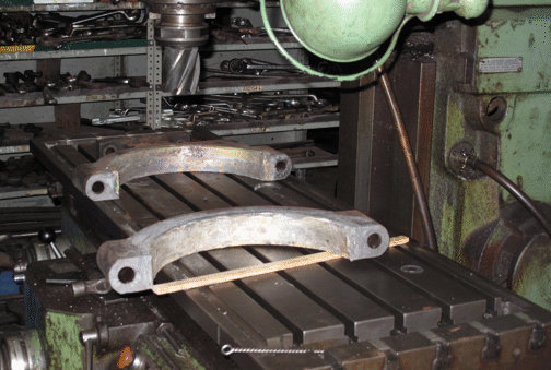
With the pistons and valves back in place, the next step was to fit the slidebars and the crossheads. The crossheads each needed to be given a coating of white metal, and this then had to be machined down so that the crossheads would be exactly the right thickness to fit between the pairs of slide bars. The same treatment was needed for the straps that fit round the eccentrics which operate the valves, and the picture below shows the two halves of one of these straps just after the white metal had been melted into place in them. They are resting on the bed of the milling machine while they cool down.
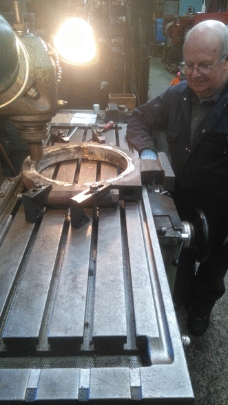
Once the two halves of each strap had cooled down, they were bolted up to form a pair, and then machining them involved two stages. The first was to mill any excess white metal off the edges of the straps, and this is being done in the picture below. The second step was then to transfer them to the lathe, and carefully machine the white metal in the inside of the straps, so that the strap would fit correctly round the eccentric.
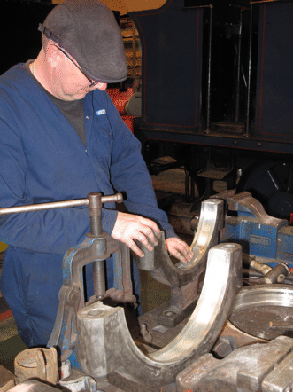
After being machined, each of the white metal bearing surfaces had to be polished smooth, using very fine emery paper. In the picture below this is being done for the inside surface of the front part of one of the four eccentric straps: the bit of the strap that is resting on the work bench is the bracket where it is bolted to the end of the eccentric rod. In front of it on the workbench is the back part of the strap, waiting for its turn to be polished, while another strap is lying on its side on the workbench.
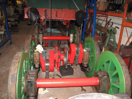
Meanwhile, the axleboxes had all been fitted back onto the axles, and the big end bearings had been fitted to the cranks on the middle axle, ready to have the connecting rods bolted to them. Also the two left-hand eccentric straps had been fitted to their eccentrics on this axle and painted, and in the picture below the brackets that attach them to the eccentric rods can be seen hanging down below them. As soon as the polishing shown above has been completed, then the two right-hand eccentric straps can be fitted and then painted. Then the next stage will be to roll the wheelsets in under the frames and carefully lower the frames down onto them.
Summer 2016
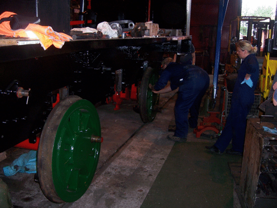
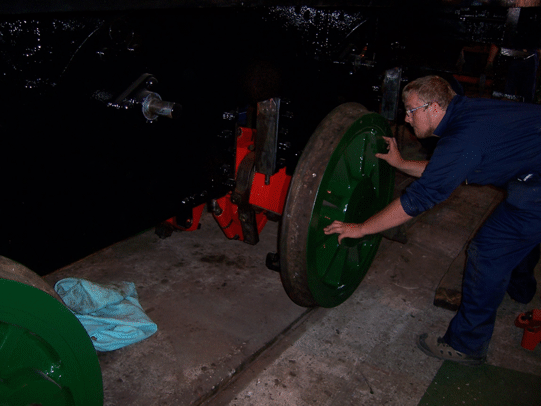
This next step happened just a couple of weeks after work started on re-tubing the boiler, which was the starting point for phase 3 of the overhaul. The lifting gantry was used to lift the rear end of the frames off their stands, and then each wheelset in turn was rolled in under the frames. In the two pictures below the front wheelset is already in position, and the middle wheelset is being rolled in.
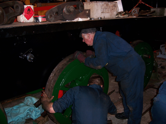
When all three wheelsets were in position, they needed to be fitted into their hornguides. For the middle wheelset this was done by lifting it up into place using the lifting gantry, and the picture below shows the wheelset being prepared for this lift.
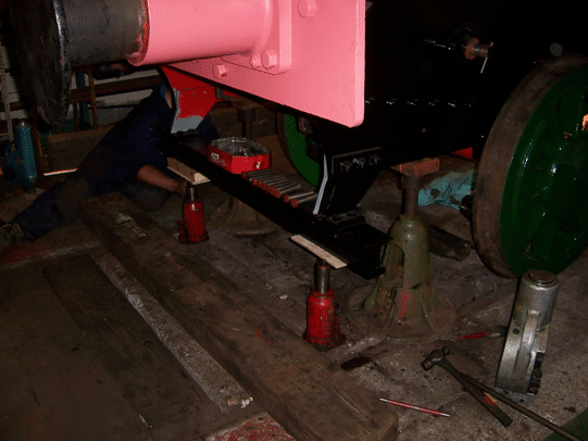
Once this wheelset had been lifted and its axleboxes engaged in their hornguides, the pins were fitted to connect the spring hangers to the frames. Then, with this wheelset in place the front end of the frames was lowered carefully, until the front axleboxes could also be engaged into their hornguides. This is the stage that had been reached in the picture below.
The olive-green bell-shaped object under the front corner of the frames in this picture is one of the stands for the frames. We have been fortunate enough to be loaned a set of four of these, which originally belonged to Hudswell-Clarke and Co. and were used by them in their erecting shop.
Attention then shifted to the rear of the frames, and they too were lowered until the rear axleboxes could similarly be engaged. Once they were, then lowering the frames continued, one end at a time, until for each pair of axleboxes the pins could be fitted to the spring hangars, so as to connect them to the frames. The picture below shows the frames at the completion of this stage, once all of the springs had been connected to them.
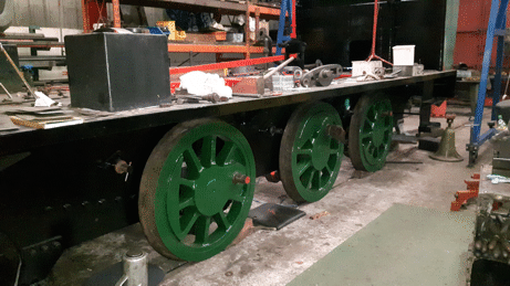
Having the frames back on the wheels effectively marked the end of phase 2 of the overhaul, since the rest of the work would be concerned with re-assembling the whole of the locomotive. The first bits of this are to refit the rest of the motion work and the brake gear, but meanwhile the focus of attention shifted to the boiler, for the start of phase 3 of the overhaul.
Go on to the next stage in this project.
Go back to the previous stage in this project.
Return to the overall description of this project.
More Information
Other pages about this project:
Other pages provide more information about:
Running Shed Phase 2 (The Pit)
As described in the page for the structure of the whole project, the Running Shed is being built in seven phases. The first of these was to obtain the necessary planning permission, and the the second involved constructing a pit that eventually would be between the rails in the shed. This was needed to allow easy access to the working parts between the frames of the locomotives, either when preparing them for service or when carrying out maintenance work on them.
We already had such a pit in the track outside where the running shed was to go, and so constructing this new pit actually just involved extending the existing one at both ends. This was all done during the first few months of 2015, and the first stage in it was to lift the track from the existing pit. This was done at the very beginning of January 2015, and then (undeterred by the weather) excavation work started on 15th January.
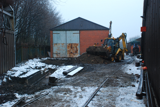
Excavation of the running shed pit in progress - it had been snowing earlier in the day, but this had stopped (just!) by the time that this picture was taken. The walls of the existing pit can be seen to the left of the picture, between the two excavated areas.
Picture © Andrew Gill, 2015.
Once the holes had been excavated, they needed to be prepared for laying the concrete base of the pit. This involved constructing wooden "shuttering" to contain the concrete at each side, and putting down a layer of sand (known as a "blinding") on top of special geo-textile (which stops mud coming up through the sand). The sand then had to be rolled firm, and steel mesh cut to shape to reinforce the concrete.
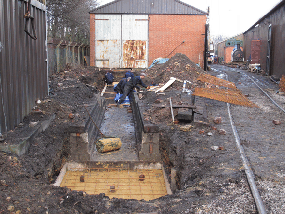
Preparing for the base of the extended pit, on 31st January. The shuttering, sand blinding and reinforcement for the southern part are in the foreground (as is the roller for the sand), and in the background the shuttering for the running shed pit is being constructed.
Picture © Tony Cowling, 2015.
Once all this preparation was complete, then the concrete could be laid, which was done on 7th February.
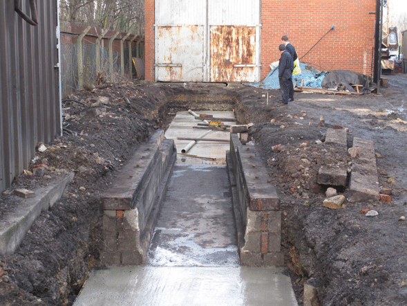
This shows the concrete base of the pit just after it had been laid. The two pieces of pipe in the background are acting as moulds, to produce drainage channels in the surface of the concrete.
Picture © Tony Cowling, 2015.
After a few days to allow the concrete of the base to cure, work could start on laying the concrete blocks that form the walls of the pit. Like the walls of the existing pit that can be seen in the picture above, each side of the pit consists of a base course of pairs of blocks laid on their sides, and then two courses on top of the base ones to form two parallel walls with a cavity between them. This cavity is then filled with concrete.
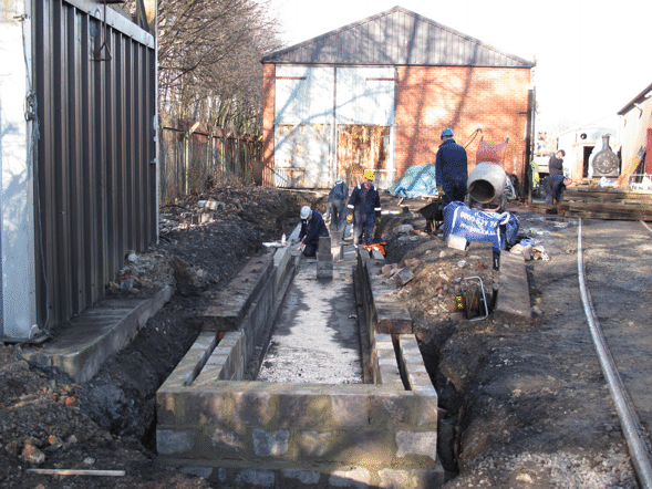
By 21st February the concrete blockwork for the south end of the pit had been constructed, and work was in progress on laying the base course of blocks for the running shed pit.
Picture © Tony Cowling, 2015.
Once the cavity between the walls had been filled with concrete, and this had cured, then the timbers that support the track on top of the walls were set in place and the chairs to hold the rails screwed down temporarily to them.
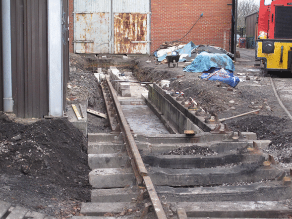
By 28th February the timbers for the south end of the pit were in place, concrete sleepers had been laid to connect the pit to the rest of the track, and one rail had been partly laid. The blocks lined up in the background are ready to be laid for the walls of the running shed pit.
Picture © Tony Cowling, 2015.
Laying the blockwork was the longest part of the job, and so while it was progressing on the part of the pit that would be in the running shed, work was also going on to complete the southern end of the pit, so that this would be available for use.
Once the timbers to support the track had been laid, and a lot of careful measuring done to make sure that the rails would be to the correct gauge (ie exactly the right distance apart) when they were put into the chairs, holes were drilled down through the timbers into the concrete, and bolts fixed into these holes in the concrete with resin adhesive. Once the adhesive had cured, then nuts could be screwed down onto the bolts to hold the timbers securely, and the chairs could be screwed down permanently onto the timbers.
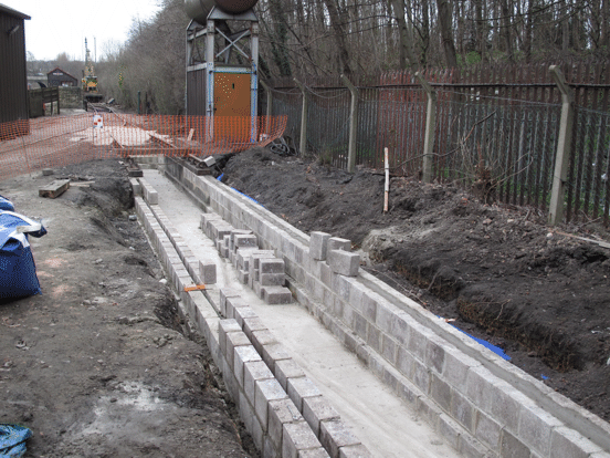
By 21st March the southern end of the pit had been completed and was available for use for preparing locomotives for service. The blockwork for the western wall of the pit was complete, and good progress had been made on the eastern wall. The blue piping that can be seen carries the supply to the water tower that is opposite the far end of the pit.
Picture © Tony Cowling, 2015.
Once all of the blockwork had been completed, then the timbers for the northern part of the pit could be laid on top of it, and the track work could be completed to connect up again with the track inside the existing workshop. This was finished in April 2015, and marked the end of phase 2 of the project.
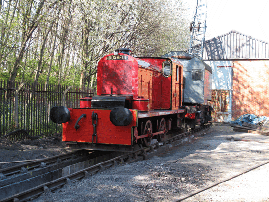
By early April the pit was complete, and HC D577 Mary is stabled on top of it, along with one of our cranes.
Picture © Tony Cowling, 2015.
For the next stages of the work, see other pages for this project.
Go on to the next stage in this project.
Go back to the previous stage in this project.
Return to the overall description of this project.
More Information
Other pages about this project and the "Buy a Brick" appeal:
- An overview of the project and the appeal;
- The "Buy a Brick" appeal;
- The structure of the project;
- The progress with the project;
- Design and site preparation;
- Construction of the foundations;
- Erection of the framework;
- Construction of the walls;
- Fitting out;
- The opening ceremony.
Other pages provide more information about:
Party Trains
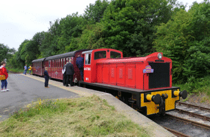
A party train at Park Halt.
Note the "Birthday Express" headboard.
When Party Trains Run
Normally party trains can run on most operating days, except when we have special events on.
If it will be of interest as to what sort of locomotive that will be pulling the train, then trains on Saturdays and Wednesdays are normally diesel hauled, and trains on Sundays and Bank Holiday Mondays are usually steam hauled.
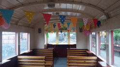
The decorated party coach.
What We Provide
For a party train we reserve and decorate one coach for your exclusive use. You or your children can enjoy the party with friends while the train travels between Moor Road and Park Halt stations on our normal passenger service. If you like you can leave the train at Park Halt and explore the ancient woodland of Middleton Park, returning to the train when you wish (but don't miss your last train back!).
Party trains run either in the morning or the afternoon, your choice! In each case the train makes three return trips. We have more detailed information sheets for you to download, please click on the time you require:
- A morning party is from 10.15 until 12.15.
- An afternoon party is from 13.15 until 15.15.
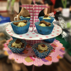
Cakes in our cafe.
Catering
You are welcome to bring your own food for consumption either on the train or at Park Halt. Hot and cold drinks and confectionery are available at our Moor Road shop.
If you wish we can arrange for food to be provided for your party, supplied by Megabites of Rothwell, from £6 per head. Please ask for further details.
We regret that your own party food can not be eaten in our cafe area, nor games played inside that area.
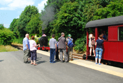
A party train at Park Halt.
Party Train Fares
The fares for a party train depend on the size of the party, as follows.
- For a party with up to 20 people (aged 1 or over), £80.
- For a party with up to 30 people (aged 1 or over), £110.
- For a party with up to 40 people (aged 1 or over), £140.
Please note that other discounted offers can not be applied to these prices.
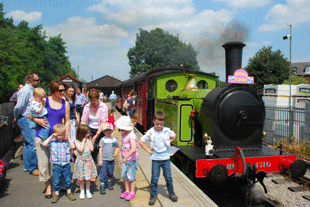
A party train at Moor Road
How to Book Your Party
All dates are offered as “subject to being available” and we operate the bookings on a first come first served basis. We regret that we do not yet have any facilities for booking party trains online. Instead, to obtain more information or to make a booking, please either:
- call in at Moor Road on any day when we are running trains and ask at our ticket desk; or
- telephone us on 07376 744 799 (but only between 9.30am and 5.30 pm, please); or
- email us on
This email address is being protected from spambots. You need JavaScript enabled to view it. .
As the Railway is run entirely by volunteers, if you telephone us there may not always be somebody available to take your call. If that is the case then please leave your name and telephone number (twice) and we will call you back at the earliest opportunity. This may be the next day on occasions.
Once you have asked to book for a particular date and time we will check to ensure that it is available. When we have made sure that it is, then we will advise you on how to pay your deposit of £30.00p. This deposit must be paid in order to secure the booking. We will hold your booking for up to five days pending payment of the deposit. After that period we can not guarantee to hold the date and time that you have requested.
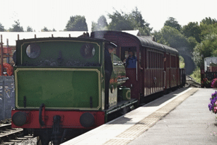
A train arriving at Moor Road
See What Others Have Said
26 July 2017.
"We held our son's 3rd Birthday here last Saturday and it was amazing! He and his friends loved every minute of it and they were all so excited!! It was non stop fun and the train carriage was perfect - we had plenty of room and being able to get off at each end was great as the end platform has a large grassed area where they can run wild for a bit and gives you time to do group pictures or play games - we did the pinata there. The staff were absolutely amazing and they all clearly love their jobs and seemed as excited as we were!! They decorated the train beautifully and hung our special banner for us and made Matthew personalised posters which they gave us to take home. So a very special thank you to all the hard working staff and Janet who managed the booking perfectly smoothly!! We will definitely be back again!!"
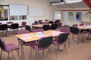
Our conference room ready for a school party
More Details
We are happy to discuss any other type of train hire or party you may have in mind, as described below.
In particular, we can make special arrangements for school parties: please see our separate page for school visits for details of these.
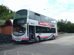
A bus waiting for a party in our car park
Tour Parties
Another form of party that we are happy to accommodate is for coach tours or similar, either to travel on one of our regular train services or (by special arrangement) on a charter train (as described below).
More details of the facilities that we can provide for such tour parties are given on our separate page for the travel trade.
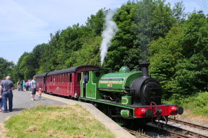
A train at Park Halt
Charter Trains
Another possible kind of special arrangement is that you may be able to charter a complete train at a time when otherwise we would not be running trains. We need a lot of notice of this, to be able to arrange crews (since they will be volunteers, like all our other staff), and we have to make a substantial charge for such trains, in order to cover the costs involved.
If you wish to find out more about the possibility of chartering a train, please email
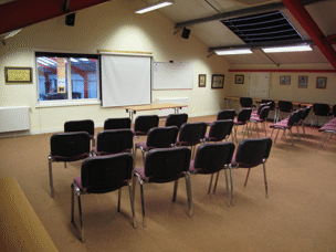
Our conference room set out for a talk.
Other Facilities Hire
As well as hiring trains, we are able to hire out our training room for meetings, for either a half day or whole day. Depending on how you want it laid out, this air-conditioned room can accommodate between 40 and 60 people; we can provide the usual audio-visual facilities, and can arrange catering if you require it.
If you wish to find out more about the possibility of hiring these facilities, please email
More Information
Other pages of our web site will provide more information about:
Buy a Brick
Helping with funding
The running shed project is a big one, and unlike previous building projects that we have undertaken there is currently no grant aid for which it would be eligible, so that we need to raise the funds for it ourselves. Even doing much of the work using our own volunteer labour, we initially estimated that we would need to raise at least £46,000 to build the Running Shed, to cover materials and the parts of the work for which we have to employ contractors.
Since then, costs have risen a bit, partly because some further bits of the work have been identified where contractors will be needed, so that we currently estimate the total cost of the project as just under £49,000. Of course, it would be nice if we could simply pay contractors to do all of the building work, but that would be even more expensive!
The fundraising appeal has now closed, so the material below about buying bricks no longer applies. But, the building is not yet finished, and so there is still scope for you to help the project by volunteering: details of this are given below.
You can help us by buying a brick at £2.50 each, and there are three ways in which you can do this:
- in person at our shop;
- by completing the donation form which can be accessed by clicking here (and will open in a new browser tab or window), and then returning this to us at: The Station, Moor Road, Hunslet, Leeds, LS10 2JQ; or
- if you are buying a number of bricks, or are buying a brick and want to have it engraved (as described below), then we can take the details by telephone (0113 271 0320), and accept payment by credit or debit card. We accept most payment cards (except American Express & Diners Card), but only for payments of more than £5.
The "brickometer" currently stands at over £18,000, which is a magnificent result, but even so we still need more!
A Name Engraved on a Brick
Another possibility which was available was to have a name engraved on a brick which will be used in the construction of the running shed. This possibility has now closed, as the last batch of bricks has had to be sent off for engraving in order for us to get them back in time to be used.
These bricks will be placed in a prominent position on the Running Shed wall. Great idea for yourself, a present or in memory of someone. But the last batch of bricks has now been sent away to be engraved, so as to ensure that they are back ready to be used in time for when bricklaying will start.
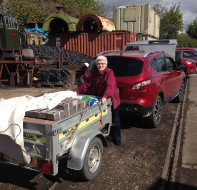
The first batch of bricks were engraved last year, and if you have ordered a brick that is in this first batch then you can view it in the shop. The picture below shows this first batch of engraved bricks, when it had been collected from the engravers in Birmingham by one of our volunteers.
Helping by volunteering
We are always happy to receive offers from anybody to contribute as a volunteer to the work of the railway. If you have particular skills that might be useful in this project then we will be particularly happy to hear from you, but don't be put off from offering if you haven't. Running the railway involves all sorts of tasks, and many of our volunteers contribute to all sorts of these. So, if you can help with some other activity, then it may free up others to put more time into this project.
Also, because the railway is run entirely by volunteers, we are very well aware of the importance of training, particularly given the historic nature of many of the technologies that we use. So, even if you do not have any particular skill that would be needed for this project, if you are willing to learn then we will be happy to try to train you.
Separate pages give more details about becoming a member of the railway and about contributing as a volunteer to any of the aspects of the work of the railway.
Following the project
To help inform subscribers to the appeal of the progress with the Running Shed project, we produced a newsletter at the beginning of March 2016 and sent this out to all donors for whom we had addresses recorded. A copy of this can be accessed by clicking this link - but it is a large file (3.2MB), and so may take a little while to download.
Also, you will be able to follow the progress of the work on the Running Shed by checking back regularly on this website. Since we are all volunteers, however, we can't promise to keep it updated in real-time! Or, you are welcome to visit the railway when it is open and ask whether you can see the progress - although this may not always be possible for safety reasons, since the site of the project is next to an area where trains may be operating.
If you have any questions about the Running Shed, or would like to discuss further sponsorship opportunities, please contact one of our volunteer team at the railway or e-mail
Go on to the next stage in this project.
Return to the overall description of this project.
More Information
Other pages about this project and the "Buy a Brick" appeal:
- An overview of the project and the appeal;
- The structure of the project;
- The progress with the project;
- The construction of the pit;
- Design and site preparation;
- Construction of the foundations;
- Erection of the framework;
- Construction of the walls;
- Fitting out;
- The opening ceremony.
Other pages provide more information about:
Subcategories
Projects
Projects and appeals.
Volunteering
For pages related to volunteering and membership

